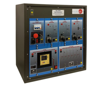
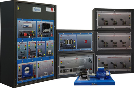
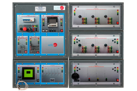
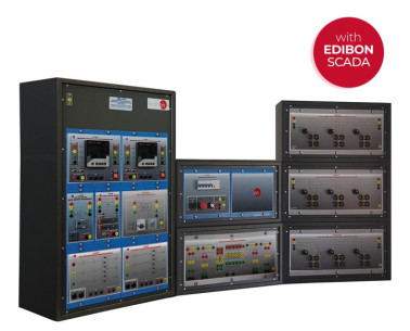
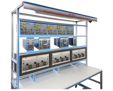
The Manual Reactive Power Compensation Application, "AEL-MRPC", has been designed by EDIBON to study the effects of reactive power consumption in AC circuits on energy efficiency, and the power factor compensation procedures that allow this problem to be solved.
For many industrial power applications, reactive power is often useful for an electrical circuit to have. While the real or active power is the energy supplied to run a motor, heat a home, or illuminate an electric light bulb, reactive power provides the important function of regulating the voltage thereby helping to move power effectively through the utility grid and transmission lines to where it is required by the load.
The power factor (PF) is defined as the ratio between the active power in watts and the apparent power in volt-amperes, and indicates how effectively electrical power is being used. The closer the power factor is to 1, the more efficient the use of the electrical power. As the apparent power is a combination of both active and reactive power, lowering the reactive power means getting closer to a power factor of value 1 without losing active power, hence, improving the efficiency of the electrical system.
While reducing reactive power to help improve the power factor and system efficiency is a good thing, one of the disadvantages of reactive power is that a sufficient quantity of it is required to control the voltage and overcome the losses in a transmission network. This is because if the electrical network voltage is not high enough, active power cannot be supplied. But having too much reactive power flowing around in the network can cause excess heating and undesirable voltage drops and loss of power along the transmission lines.
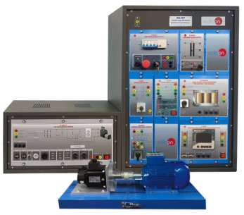
Also, in real power systems the majority of loads are of inductive nature, so they require some amount of reactive power for them to function. A capacitor or bank of capacitors installed parallel to the load provides this reactive power. They act as a source of local reactive power, and thus less reactive power flows through the line. Capacitor banks reduce the phase difference between the voltage and current.
The "AEL-MRPC" application includes all types of commutable loads (resistive, inductive and capacitive) to study the power factor correction. A network analyzer is also included to measure the electrical parameters (currents, voltages, frequency, powers or the power factor) that the user must have access to in order to perform a correct study of the power factor compensation.
 Cookie preferences

 Catalog
 Tender Specifications