AFT Fluid Friction in Pipes Unit, with Hydraulics Bench (FME00)

FLUID FRICTION IN PIPES UNIT, WITH HYDRAULICS BENCH (FME00) - AFT

INNOVATIVE SYSTEMS

The Fluid Friction in Pipes Unit, with Hydraulics Bench (FME00), "AFT", has been designed by EDIBON to determine the friction coefficient in pipes of several diameters and roughness, to study the pressure losses in different types of valves and different fittings and to compare different methods to measure the flow.

See general description

RELATED NEWS

General Description

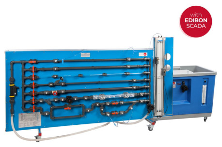
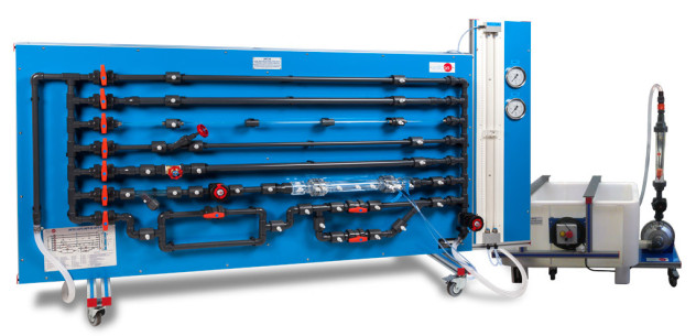
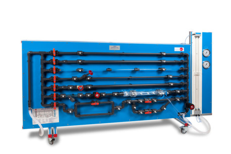
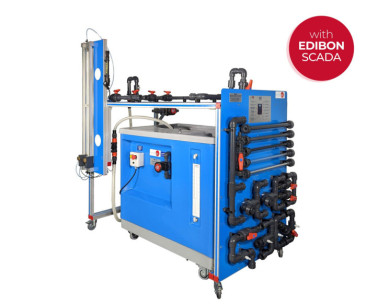
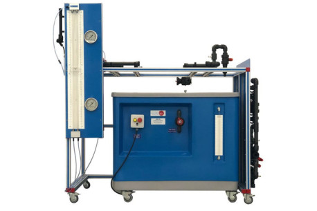
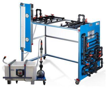
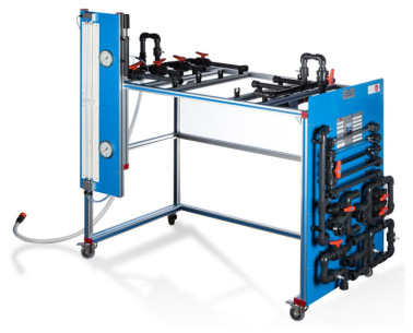
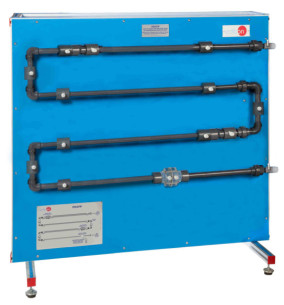
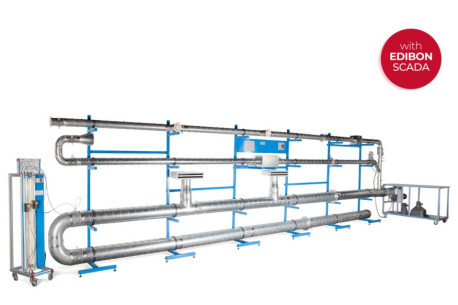
The unit Fluid Friction in Pipes Unit, with Hydraulics Bench (FME00), "AFT", contains six straight pipe sections made of different materials and with different diameters and roughness. Additionally, a wide range of accessories are included for the study of losses in straight pipes, several types of valves (gate, ball, angle seat, etc.), pipe fittings (in-line strainer, elbows, sudden widening, contraction, etc.) and measuring elements (Venturi tube, Pitot tube, orifice plate flowmeter, flow measuring nozzles, etc.).

Some of the measuring elements, like the Venturi tube, Pitot tube, etc., are transparent to observe their function.

The different pipe sections, valves and pipe fittings include several pressure measurement points with quick action connections to fit the tubing that is connected to the corresponding pressure measuring device.

With this unit friction pressure losses can be investigated over a wide range of Reynolds numbers, thereby covering the laminar, transitional and turbulent flow regimes. Two water manometric tubes allow to study the pressure losses in the laminar regimen. Two Bourdon manometers allow to obtain the pressure losses in the turbulent regimen. Additionally, it includes a flowmeter to measure and to compare measurements of flow with the Venturi tube and the Pitot tube.

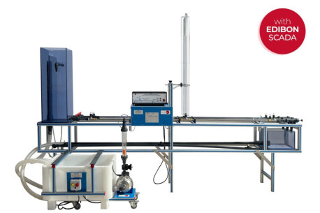
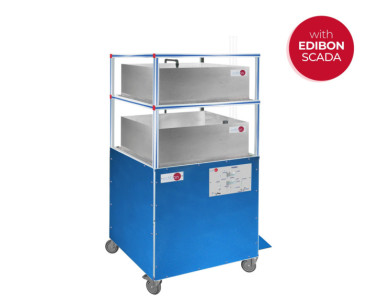
The unit includes the Hydraulics Bench, "FME00", which incorporates a sump tank and a centrifugal pump to make water flow in a close circuit and to supply it to the "AFT" unit, allowing an independent operation of the unit.

Exercises and guided practices

GUIDED PRACTICAL EXERCISES INCLUDED IN THE MANUAL

Obtaining pressure drops in different types of pipes:

  1. Determination of pressure loss due to friction in a rough pipe with an internal diameter of 17 mm.
  2. Determination of pressure loss due to friction in a rough pipe with an internal diameter of 23 mm.
  3. Determination of pressure loss due to friction in a smooth pipe with an internal diameter of 6.5 mm.
  4. Determination of pressure loss due to friction in a smooth pipe with an internal diameter of 16.5 mm.
  5. Determination of pressure loss due to friction in a smooth pipe with an internal diameter of 26.5 mm.

Comparison of the different parameters that affect pressure drops:

  1. Study of the influence of the diameter in the pressure loss due to friction in rough pipes.
  2. Study of the influence of the diameter in the pressure loss due to friction in smooth pipes.
  3. Study of the influence of the roughness in the pressure loss.
  4. Determination of the friction coefficient in a rough pipe with an internal diameter of 17 mm.

Calculation of the friction coefficient in different types of pipes:

  1. Determination of the friction coefficient in a rough pipe with an internal diameter of 23 mm.
  2. Determination of the friction coefficient in a smooth pipe with an internal diameter of 6.5 mm.
  3. Determination of the friction coefficient in a smooth pipe with an internal diameter of 16.5 mm.
  4. Determination of the friction coefficient in a smooth pipe with an internal diameter of 26.5 mm.

Influence of different parameters in the friction coefficient:

  1. Study of the influence of the diameter in the friction coefficient in rough pipes.
  2. Study of the influence of the diameter in the friction coefficient in smooth pipes.
  3. Comparison of the friction coefficient in smooth and rough pipes.

Obtaining the pressure drop in different types of valves:

  1. Determination of pressure loss in an angle-seat valve.
  2. Determination of pressure loss in a gate valve.
  3. Determination of pressure loss in a diaphragm valve.
  4. Determination of pressure loss in a ball valve.

Comparison between different types of valves:

  1. Comparison of pressure loss in different types of valves.

Obtaining the pressure drop in different types of fittings:

  1. Determination of pressure loss in an in-line strainer.
  2. Determination of pressure loss in a 90° elbow.
  3. Determination of pressure loss in a double 90° elbow.
  4. Determination of pressure loss in a 45° elbow.
  5. Determination of pressure loss in a 45° "T".
  6. Determination of pressure loss in an inclined T.
  7. Determination of pressure loss in a symmetrical "Y" branch.
  8. Determination of pressure loss in a narrowing.
  9. Determination of pressure loss in a gradual widening.
  10. Determination of pressure loss in a diaphragm.

Comparison between different types of fittings:

  1. Comparison of pressure loss in the different fittings.

Flow measurement through different systems:

  1. Measurement of the flow with the Venturi tube.
  2. Determination of the discharge coefficient, Cd, in the Venturi tube.
  3. Measurement of the flow with the Pitot tube.
  4. Determination of the discharge coefficient, Cd, in the Pitot tube.

Comparison between different systems:

  1. Comparison between the flow measured in the Venturi and Pitot tubes.
View more

MORE PRACTICAL EXERCISES TO BE DONE WITH THE UNIT

  1. Study of the relationship between pressure losses due to fluid friction and the water flow rate.
  2. Determining the relationship between the pipe friction coefficients and Reynolds number for flow through a pipe with roughened bore.
  3. Determining of the resistance coefficients for bends, enlargements and contractions.
  4. Determining of characteristic curves of valves and fittings.

INCLUDED ELEMENTS

SIMILAR UNITS AVAILABLE

Quality

AFTER-SALES SERVICE

Ask for information