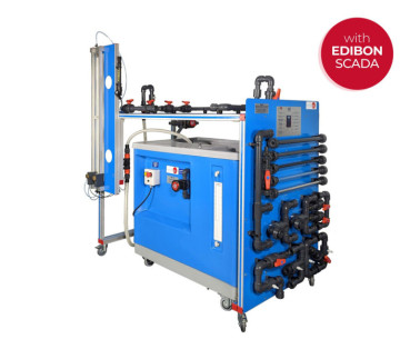
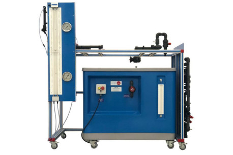
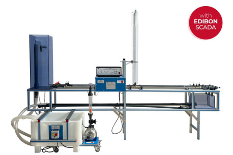
The Computer Controlled Fluid Friction in Pipes, with Hydraulics Bench (FME00), "AFTC", is designed to determine the friction coefficient in pipes of several diameters and roughness, to study the pressure losses and pressure development in different types of valves and fittings and to compare different methods to measure the flow.
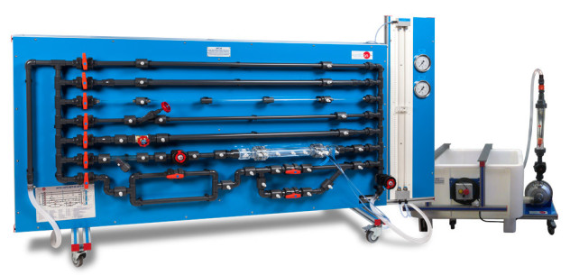
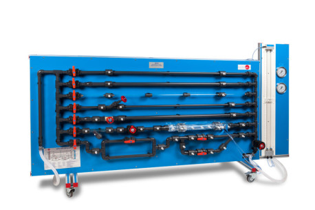
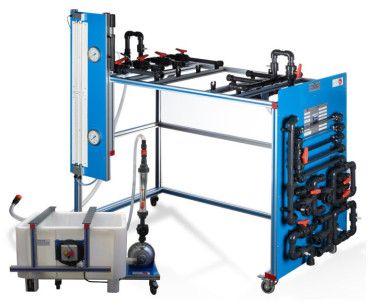
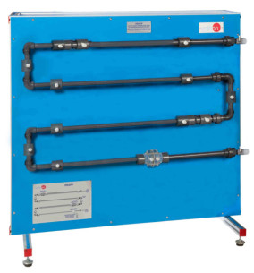
The unit contains six horizontal straight pipe sections made of different materials and with different diameters and roughness to study their influence in the pressure losses.
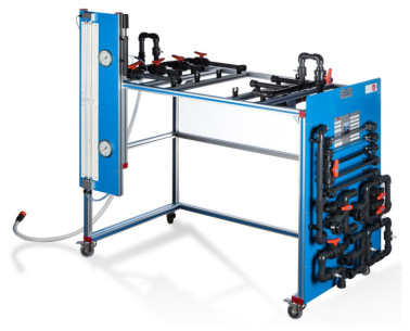
Additionally, a wide range of accessories are included for the study of losses in straight pipes, several types of valves (gate, ball, angle seat, etc.), pipe fittings (mesh filter, elbows, sudden widening, contraction, etc.) and measuring elements (Venturi tube, Pitot tube, orifice plate flowmeter, flow measuring nozzles, etc.).
Some of the measuring elements, like the Venturi tube, Pitot tube, etc., are transparent to observe their function.
The different pipe sections, valves and pipe fittings include several pressure measurement points with quick action connections to fit the tubing that is connected to the corresponding pressure measuring device.
The sections can be exchanged without tools.
With this unit pressure losses can be investigated over a wide range of Reynolds numbers, thereby covering the laminar, transitional and turbulent flow regime. Two water manometric tubes and two displacement sensors allow to study the pressure losses in the laminar regime.
Two pressure sensors allow to obtain the pressure losses in the turbulent regimen. Additionally, it includes a flow sensor to measure and to compare measurements of flow with the Venturi tube and the Pitot tube.
Annular chamber shaped measuring points are located around the measuring elements for an accurate pressure measurement.
The unit includes the Hydraulics Bench (FME00), which incorporates a sump tank and a centrifugal pump to make water flow in a close circuit and to supply the "AFTC" unit, allowing an independent operation of the unit.
A flow sensor measures the flow impelled by the pump.
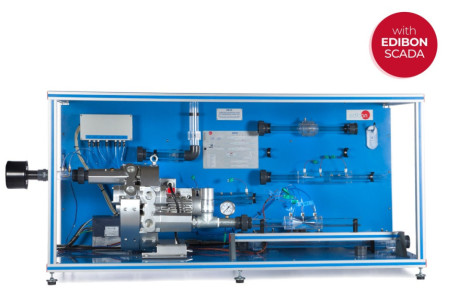
This Computer Controlled Unit is supplied with the EDIBON Computer Control System (SCADA), and includes: The unit itself + a Control Interface Box + a Data Acquisition Board + Computer Control, Data Acquisition and Data Management Software Packages, for controlling the process and all parameters involved in the process.
 Cookie preferences
 - AFTC")
 - AFTC")
 - AFTC")
 - AFTC")
 - AFTC")
 - AFTC")
 - AFTC")
 - AFTC")
 - AFTC")
 - AFTC")
 - AFTC")
 - AFTC")
 Catalog
 Tender Specifications


 - AFTC")