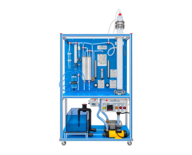
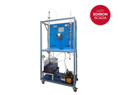
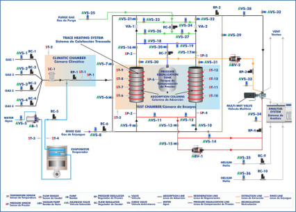
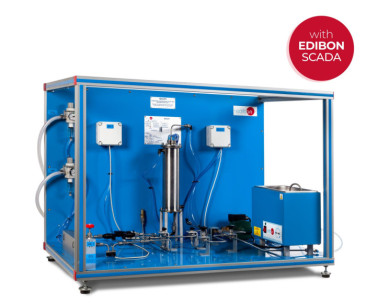
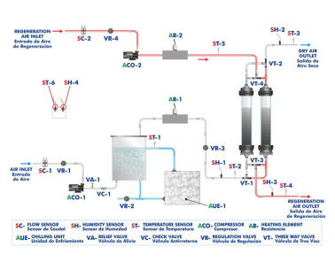
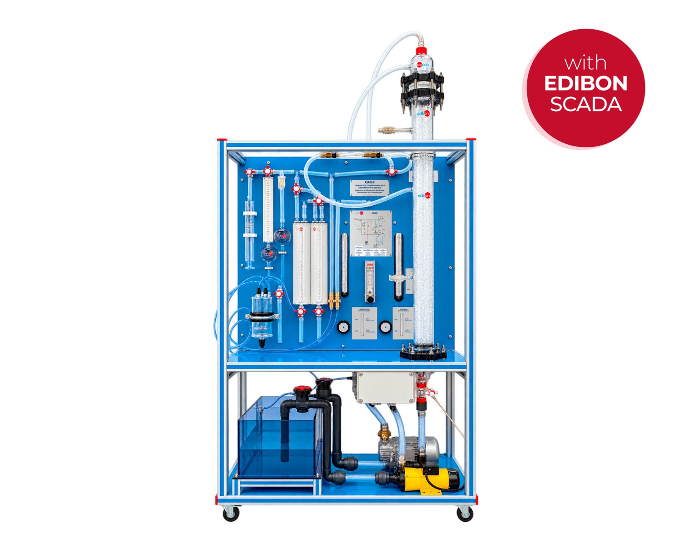
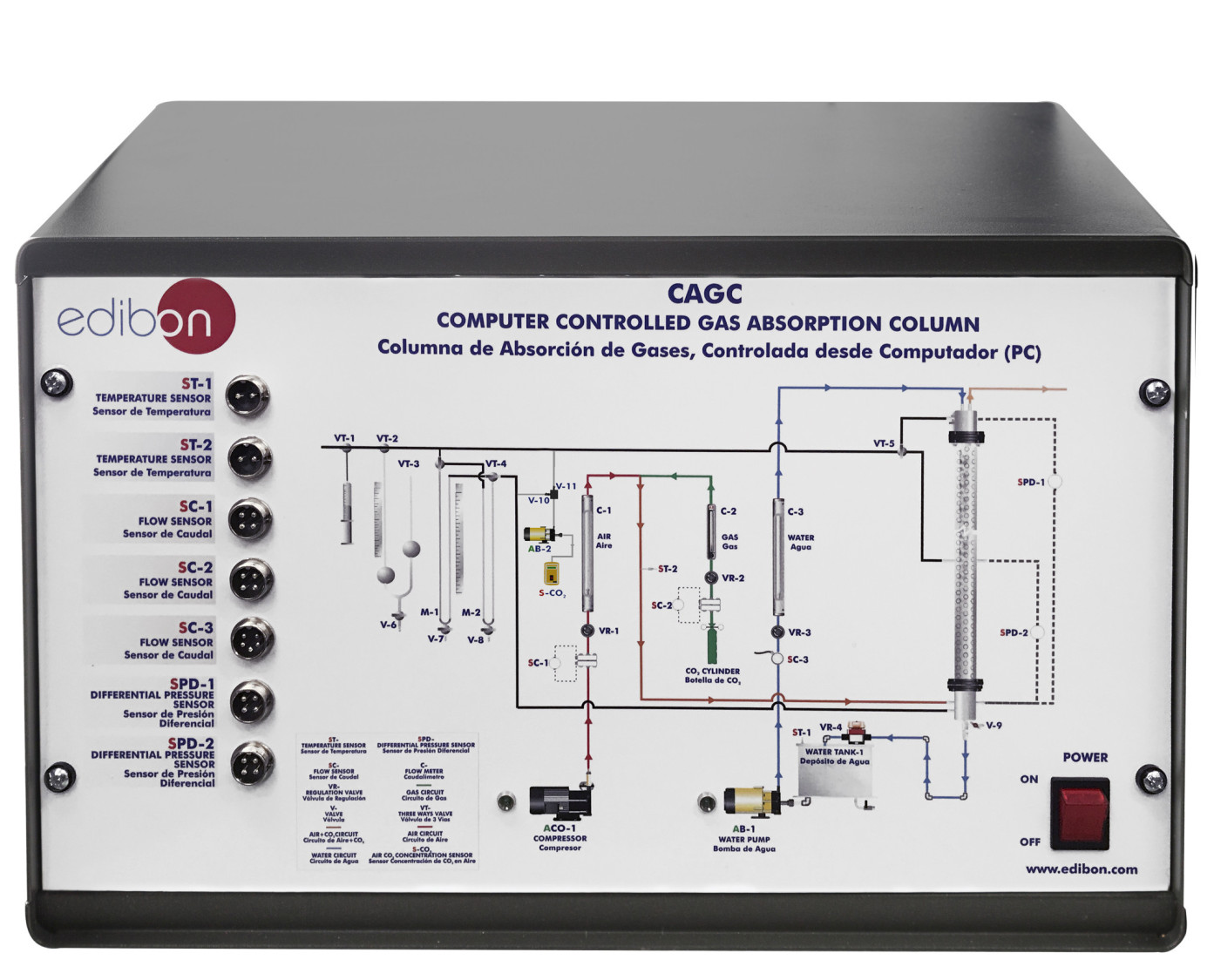
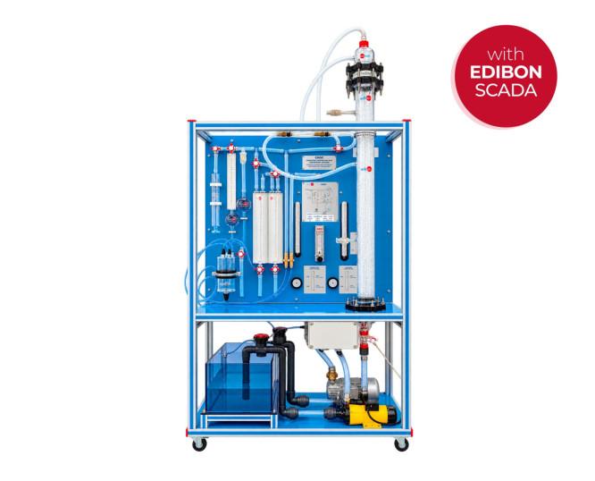
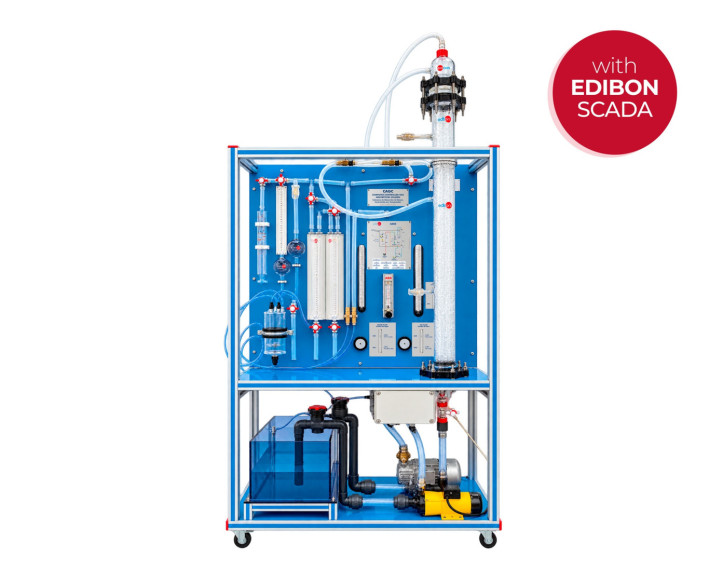
The Computer Controlled Gas Absorption Column, "CAGC", has been designed by EDIBON to experimentally reproduce gas absorption processes in a packed column through countercurrent contact between a gas mixture of air and CO₂ or ammonia and a downward-flowing water stream. The unit enables the study of the hydrodynamic behavior of both phases, the determination of entrainment and flooding conditions, the evaluation of mass transfer, and the verification of mass balances. It also allows the influence of operating conditions on absorption efficiency to be analyzed by adjusting flow rates and measuring the main process variables.
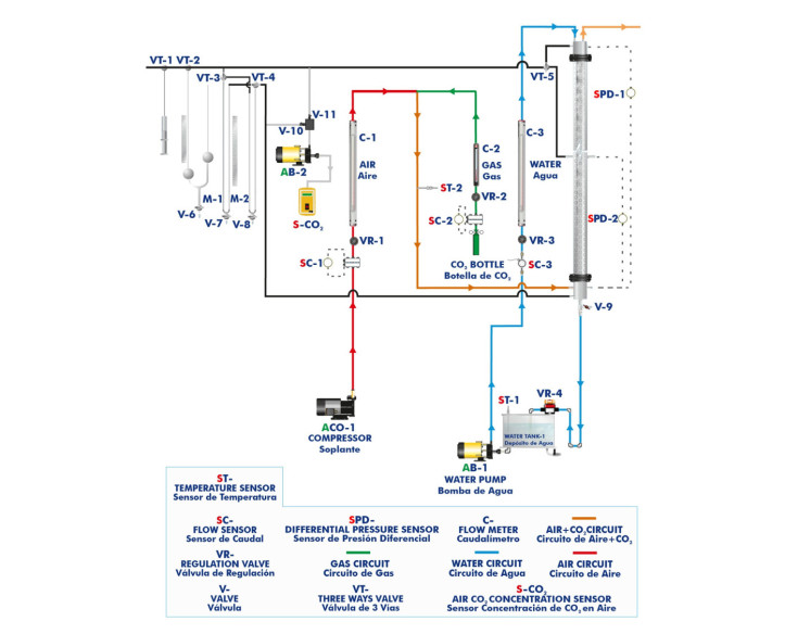
The process takes place in a cylindrical glass column packed with Raschig rings, which provide the contact surface between the gas and liquid phases. Its transparent construction allows the fluid behavior throughout the packed bed to be observed. The column includes connections for the inlet and outlet of both phases, sampling ports, and two differential pressure sensors that enable pressure drops to be analyzed at different sections and the hydrodynamic behavior of the column to be characterized as a function of operating flow rates.
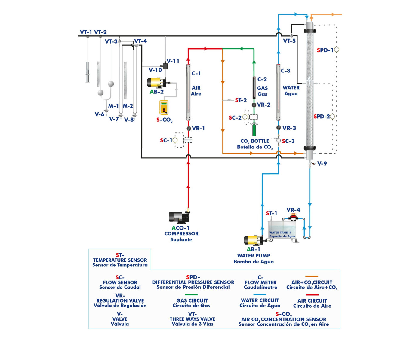
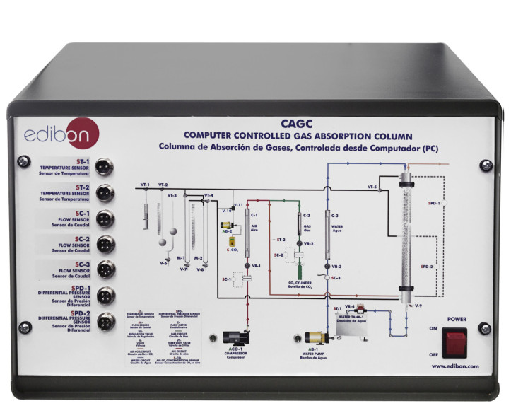
The liquid circuit begins in a water storage tank, from which a computer-controlled centrifugal pump delivers the liquid to the top of the column. A glass spray distributor distributes the water over the packing, promoting its downward flow and contact with the rising gas stream. The flow rate is measured using a flow sensor and a flowmeter and can be regulated through computer-controlled PID control. A temperature sensor measures the water temperature at the column inlet. After passing through the packed bed, the liquid returns to the storage tank through a pipe equipped with a regulating valve and a sampling port. The tank also allows CO₂ desorption to be studied by aerating the water previously loaded during the absorption process.
The gas circuit combines an air stream supplied by a computer-controlled compressor with a CO₂ or ammonia stream from an external gas cylinder, which is not included in the supply. Both streams are equipped with flow regulation and measurement instrumentation consisting of differential pressure sensors and flowmeters. After mixing, the gas enters through a lateral inlet at the bottom of the column, below the packed bed, promoting homogeneous distribution before beginning its upward flow. A temperature sensor measures the temperature of the gas mixture at the inlet. Independent adjustment of the air, gas, and water flow rates allows their influence on phase contact, pressure drops, and absorption efficiency to be analyzed.
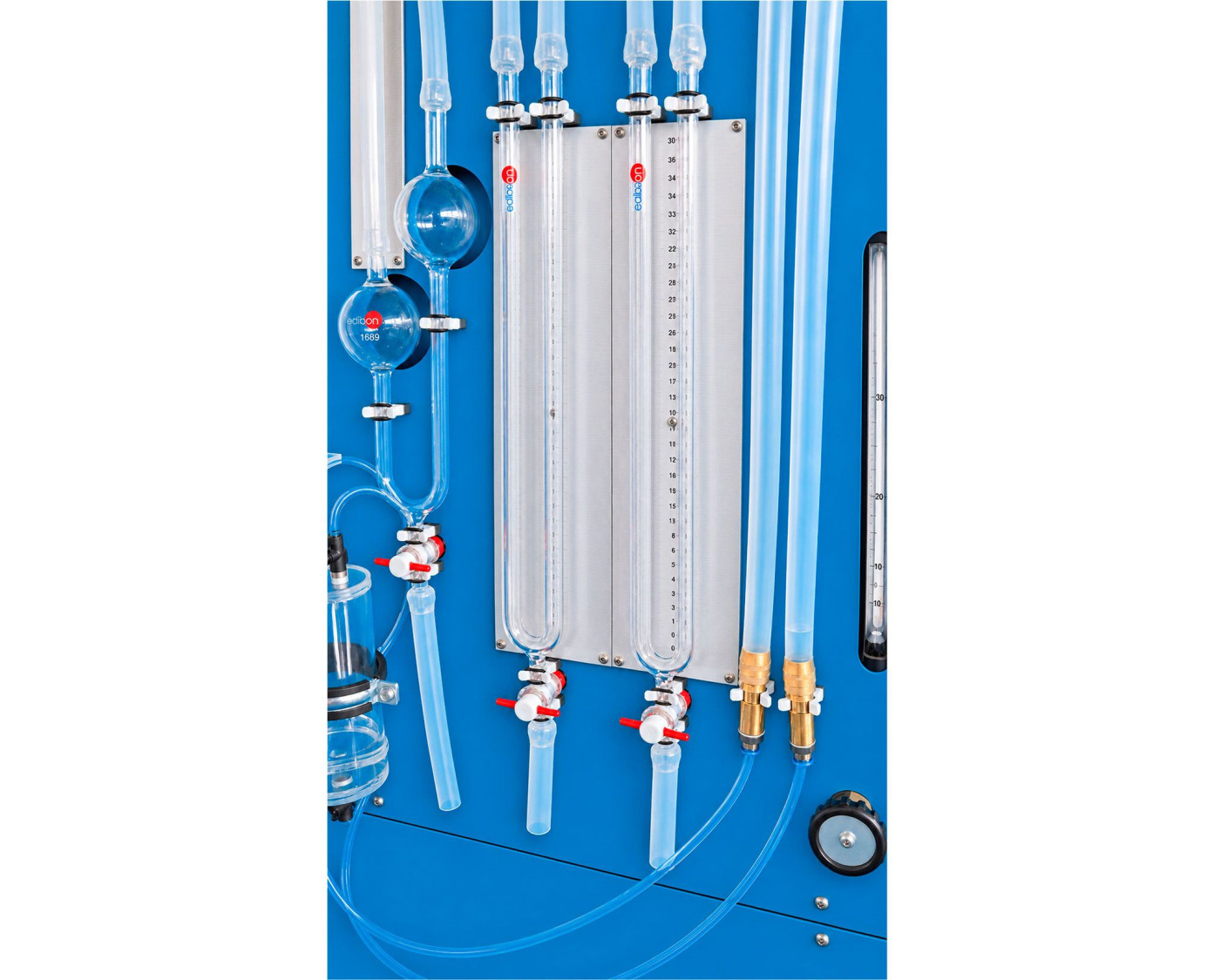
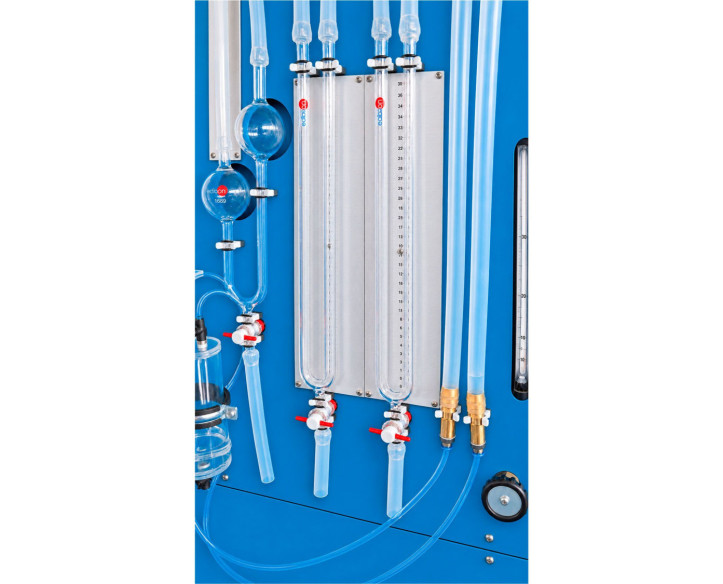
For CO₂ analysis in gas streams, the Unit provides two complementary measurement methods. Analytical determination is performed by extracting gas samples and bringing them into contact with an aqueous potassium hydroxide (KOH) solution, which absorbs the CO₂ contained in the samples. This procedure uses a glass syringe to obtain a defined sample volume, two interconnected glass vessels positioned at different heights, three-way valves to direct the gas streams, and a computer-controlled vacuum pump. Alternatively, a CO₂ concentration sensor allows direct measurements in the gas streams. Sampling ports located in the upper and central sections of the column enable the evolution of CO₂ concentration throughout the absorption process to be analyzed. The concentration analysis instrumentation described is specifically intended for CO₂.
The combination of flow rate, temperature, differential pressure, and concentration measurements enables gas-liquid mass transfer studies, determination of mass transfer coefficients, verification of mass balances, and evaluation of the variables affecting process efficiency. It also allows the hydrodynamic characteristics of the packing to be analyzed, entrainment and flooding conditions to be identified, water flow sensor hysteresis to be studied, and sensor calibration exercises to be performed.
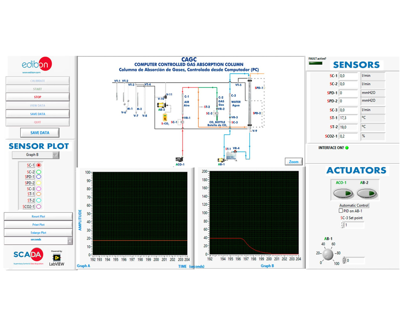
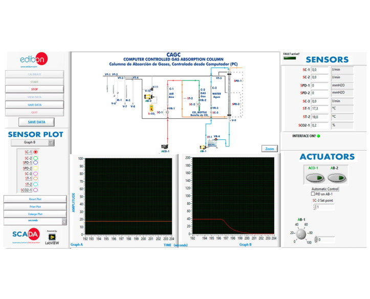
The Unit incorporates open control, multivariable control, and real-time control functions, with computer-based acquisition and visualization of measured variables. It allows the water pump, air compressor, and vacuum pump to be controlled, as well as the proportional, integral, and derivative parameters of the PID controller to be modified and their response studied. Additionally, the process can be controlled through the control interface without using a computer.
Additionally, in order to expand the experimental possibilities, different recommended additional elements can be incorporated:
- Manual CO₂ Concentration Meter for Gas Streams, "CAG/M": enables the CO₂ concentration in gas streams to be measured.
- Cooling Water Recirculation Unit, "TERA": enables the influence of temperature on absorption efficiency to be studied.
This Computer Controlled Unit is supplied with the EDIBON Computer Control System (SCADA), and includes: The unit itself + a Control Interface Box + a Data Acquisition Board + Computer Control, Data Acquisition and Data Management Software Packages, for controlling the process and all parameters involved in the process.
 Cookie preferences



 Catalog
 Tender Specifications