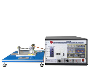
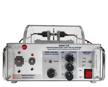
The Computer Controlled Advanced Industrial Servosystem Unit (for DC Motors), "SERIN/CC", has been designed by EDIBON to allow to perform different practices related to servomotors to be carried out. The unit has different modules to develop different experiments. The modules included in the "SERIN/CC" unit are:
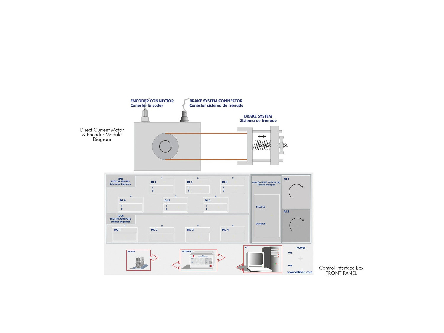
- Digital inputs and outputs: the unit contains six digital inputs and four digital outputs. The digital inputs can be used to trigger different defined standard functions as well as defined motion profiles. The digital outputs give all necessary information about the status of the motion.
- Analog inputs: The device has two analogue inputs that can be enabled or disabled using the switch. They have a voltage range of 0 – 5 Vdc and have a resolution of 10 bits.
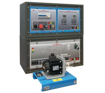
- DC motor: the motor is connected to a tensioning brake that can be used to load the motor.
The interface has a servomechanism controller for DC motors that controls the speed, position and current of the motor. A pulse encoder is used for this feedback control.
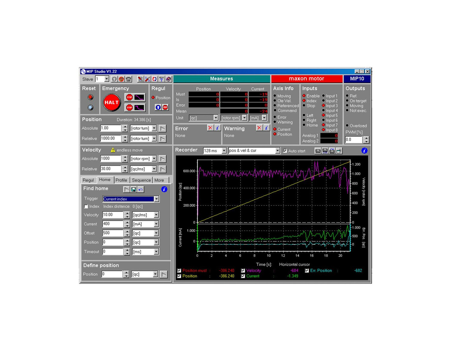
The RS232 communication between the interface and the computer gives the "SERIN/CC" unit the possibility to control the motor from the computer and to display the most important signals of the motor.
The 4-quadrant servo controller controls the operation of the motor and braking in both clockwise and counterclockwise directions of rotation for correct positioning.
The controller is a pulse width modulator (PWM) in which the controller turns the motor on and off many times per second (several tens of thousands of times). If the switch-on interval is longer, the motor gains speed, but if the switch-on interval is shorter, the motor loses speed. The decisive average value of the voltage changes in relation to the time-on-off in one cycle of the PWM signal. This type of control has a higher efficiency and only a minimum of energy is converted into heat.
There are three types of controls performed by the controller:
- Speed control: The speed function of the servo amplifier is to maintain a constant motor speed independent of load changes. For this purpose the set point (desired speed) is continuously compared with the actual value (actual speed) in the electronic control of the servomechanism of the amplifier. The controller difference determined in this way is used by the controller to regulate the pulse width of the servo amplifier in such a way that the motor reduces the controller difference. This represents a closed-loop speed regulation circuit.
- Position control: Position control ensures that the position obtained from the current measurement matches the target position by providing the motor with corresponding correction values, just as the speed controller does. This position is usually obtained from a digital encoder.
- Current or torque control: Current control provides the motor with a current proportional to the set point. Therefore the motor torque changes proportionally to the set point. Current control also improves the dynamics of an overriding positioning or speed control circuit.
The motor is equipped with a digital encoder providing 500 pulses per revolution. The direction of rotation is detected with the square pulses of channels A and B through an electrical 90-degree offset.
The digital encoder is used in position control to derive and measure the displacement or angle.
The encoder provides a simple square signal for further processing of the control system. Its pulses can be counted for exact positioning or velocity determination. Channels A and B generate out-of-phase signals, which are compared to determine the direction of rotation.
The so-called "home" pulse (channel I) provides a zero crossing and is used as a reference point to precisely determine the angle of rotation.
The encoder of the "SERIN/CC" unit evaluates the rising and falling edges of the signal. In consideration of the number of encoder pulses, this result gives four times more accurate positioning.
 Cookie preferences
 - SERIN/CC")
 - SERIN/CC")
 - SERIN/CC")
 - SERIN/CC")
 - SERIN/CC")
 - SERIN/CC")
 Catalog
 Tender Specifications


 - SERIN/CC")