 Cookie preferences
Your selection
There are no more selected items


 Catalog
 Tender Specifications


- LIFLUBA
Available
8.1.7.- HYDRAULIC MACHINES: TURBINES
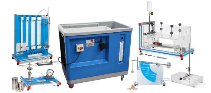
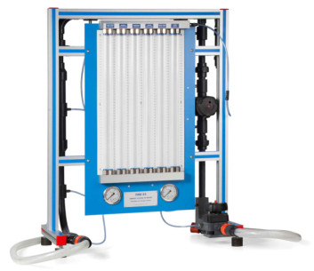
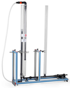
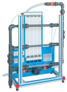
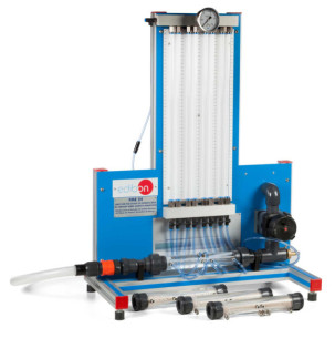
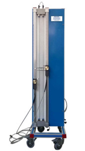
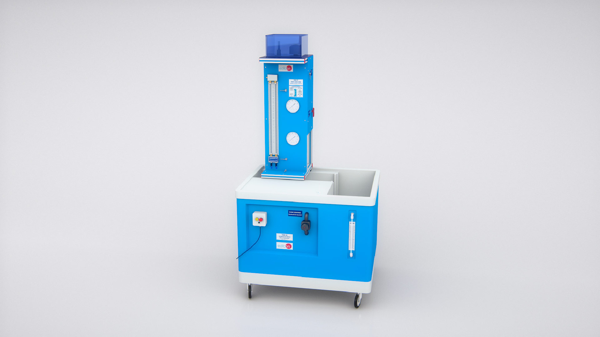
LIFLUBA
Basic Fluids Mechanics Integrated Laboratory
Hydraulics is the branch of science that deals with the mechanical properties of fluids, and Fluid Mechanics provides the foundation for hydraulics.With LIFLUBA (Basic Fluids Mechanics Integrated Laboratory), EDIBON tries to give answer to the...


