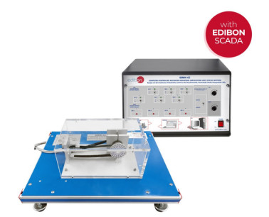
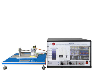
The Servosystems Basic Unit for DC Motors, "SERIN/CCB", is an unit whose goal is studying low power servo systems. It is a low power DC motor speed control trainer that has a breakdown simulator.
This unit is a basic version of the Computer Controlled Advanced Industrial Servosystem Unit (for DC Motors), "SERIN/CC", being advisable for an introductory study of closed and open loop control systems.
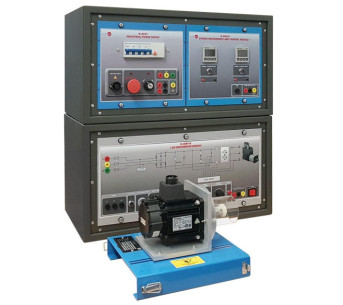
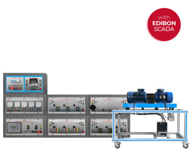
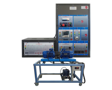
It consists of an electromechanical unit with an DC motor and a tachometer, attached through an inertial wheel, mounted on a steel box that contains the power stage and the acquisition and control board, as well as the supervision and control software.
This set allows open and closed loop control, control and generation of command variable, ramp generator, proportional error amplifier and PID, current limiter, PWM modulator, turn inversion control, start and stop control, braking control, and breakdown simulator, that allows introducing a great number of dysfunctions so that students may diagnose nature and location of the fault, without risking the integrity of the unit.
Unit control may be done manually, on the unit itself, basically or in a more advance way through the control software SCADA. This control software can do two kinds of control:
Open-loop and Closed-loop control.
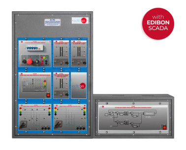
The base unit has four different parts as seen on the front panel:
Connection zone for motor and tachogenerator.
Manual or Compute rised Speed control. There is a lever-like switch for selecting the kind of control.
PID zone. Here, the values of the PID constants can be manipulated (Proportional, Integral and Derivative). This functionality is only available for PC mode, the speed control lever has to point to PC.
Turning and stop control zone. Allows changing the turning sense and stopping the motor.
Simple integrated circuits to be able to analyse independently each functional stage.
Visible components with 2 mm connectors for voltage and current measurement.
Control through PWM pulses and power stage configured with MOSFET transistors.
 クッキーの設定

 カタログ
カタログ
 コンテストの仕様