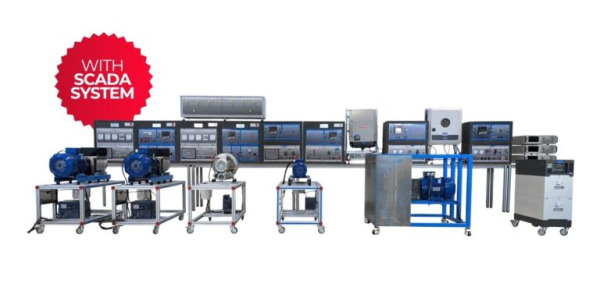
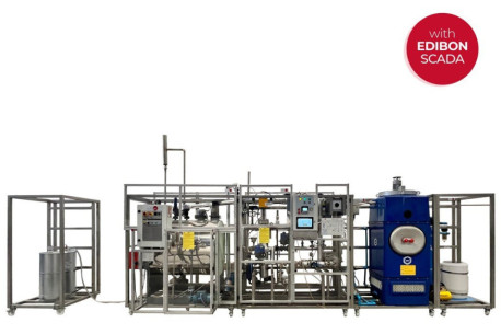
The Computer Controlled and Touch Screen 20 kW Steam Power Plant,"TPTV/20kW/CTS", allows the detailed study of the power generation cycle using steam as process fluid.
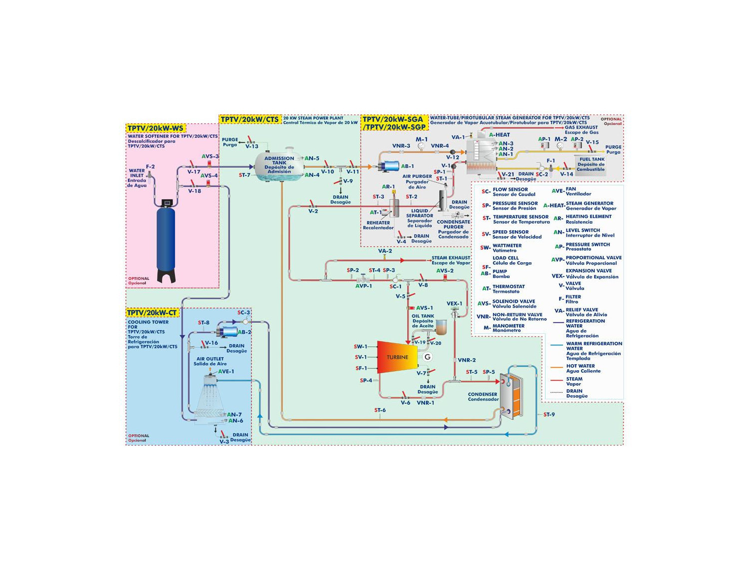
In addition to the main TPTV unit, the unit has three required units, Water Softener for TPTV/20kW/CTS, "TPTV/20kW-WS", Cooling Tower for TPTV/20kW/CTS, "TPTV/20kW-CT", and Water-tube Steam Generator for TPTV/20kW/CTS, "TPTV/20kW-SGA" or Pirotubular Steam Generator for TPTV/20kW/CTS, "TPTV/20kW-SGP", which allow optimization of the unit and increase the degree of similarity of the 20 kW Steam Power Plant with a real steam power generation plant.
The incorporation of the Water Softener for TPTV/20kW/CTS, "TPTV/20kW-WS" makes it possible to eliminate the hardness of the mains water by incorporating a 40 l column of ion exchange resin, which retains the lime present in the water, exchanging the calcium cations for sodium cations. The decalcified water can flow into the Cooling Tower for TPTV/20kW/CTS, "TPTV/20kW-CT", or into the intake tank and, subsequently, into the Steam Generator of choice, ("TPTV/20kW-SGA" or "TPTV/20kW-SGP"), tank.
The decalcified water is stored in the Cooling Tower for TPTV/20kW/CTS, "TPTV/20kW-CT". If the water level is below the level switch AN-6, the unit will automatically fill the unit by opening the automatic valve AVS-4 until the level switch AN-7 is reached.
In case the water level is correct, the water is pumped to the condenser of the Steam Power Plant, "TPTV", to condense the expanded steam in the turbine, thus allowing the condensate to be returned to the intake tank. The refrigeration tower tank can be emptied manually by means of valves V-3 and V-16.
The inlet tank can therefore be filled directly with decalcified water at the start-up of the unit or it can be filled with the condensate return. In both cases, the purge valve V-13 must remain open to remove air from the tank and facilitate filling. If there is no water available, the AVS-3 valve will be opened, allowing the tank to be filled up to the level switch AN-5. The tank can be emptied manually by means of valves V-9 and V-10.
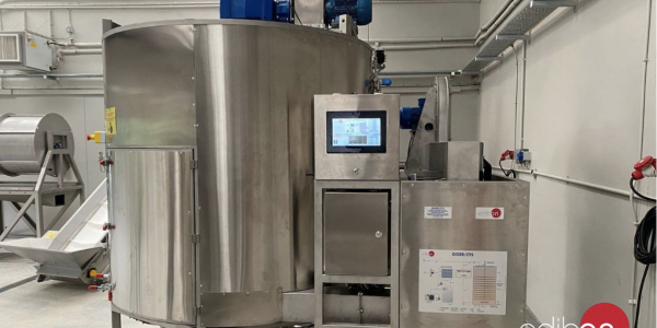
If the liquid level is sufficient, the water is pumped to the boiler. In the boiler, the water is progressively heated and pressurised by the diesel combustion process until the desired vapour conditions are obtained.
Once the process conditions are obtained, the steam passes through a liquid separator to remove any suspended droplets present in the steam generated in the Steam Generator of choice, ("TPTV/20kW-SGA" or "TPTV/20kW-SGP"). Once dry, the steam is reheated by passing through the installation’s resistance to obtain superheated steam.
To regulate the steam flow rate of the circuit, the installation has a proportional valve that throttles the flow rate of the installation, allowing it to operate in a wide range of steam flow rates. After passing through the proportional valve, the steam can take two different paths.
The first path allows the turbine to be bypassed by opening the AVS-2 valve, thus ensuring the integrity of the turbine until the desired process conditions are obtained. This bypass flows into the condenser where the steam is condensed, closing the cycle.
The second path allows the turbine to extract thermal energy from the steam, converting it into mechanical energy, which is converted into electrical energy by the generator. The rotational speed of the turbine, as well as the torque and the power generated are measured by different sensors in the turbine.
In order to optimize the rotation of the turbine, the turbine is equipped with a lubrication reservoir. In order to remove any condensation that may occur during the first moments of contact between the steam and the cold blades of the turbine, the turbine is equipped with a drain valve.
This computer controlled unit is supplied with the EDIBON Control System (SCADA), and includes: The unit itself + CTS + Control, Data Acquisition and Data Management Software Packages, for controlling the process and all parameters involved in the process.
 Cookie preferences


 Catalog
 Tender Specifications


