AEL-GPRE 発電機保護リレーの適用

GENERATOR PROTECTION RELAY APPLICATION - AEL-GPRE

革新的なシステム

The Generator Protection Relay Application, "AEL-GPRE", has been designed by EDIBON for the training at both the theoretical and practical levels in the field of high power generators with control and protection systems.

一般的な説明を表示

概要

The Generator Protection Relay Application, "AEL-GPRE", has been designed by EDIBON for the training at both the theoretical and practical levels in the field of control and protection systems of high power generators.

This application presents several levels of training to give the user full knowledge and experiences about the operation of advanced protection systems used in large power plants with electrical generators: a specific manual in which are theoretically studied all aspects related to electrical generators such as types of electrical generators, basic principles of generators operation, control and stand-alone generator operation, parallel generator operation with the national grid, types of protections used to protect these machines, sizing and protection relay settings. In order to achieve all the practices and concepts mentioned above, a series of elements are listed and explained below, which are either included in the main equipment or are recommended to complete a series of practices that are of interest in this area and that the user will have to additionally acquire.

The "AEL-GPRE" application includes a series of modules that make it leadership in the market:

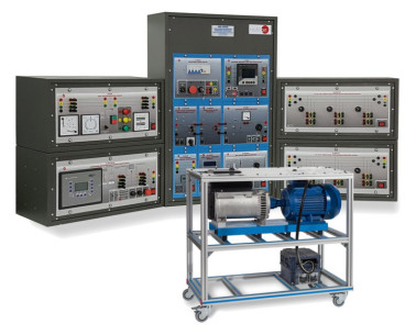
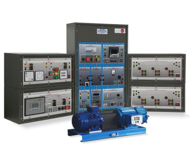
  • The Generator Protection Relay Module: it is an industrial control and protection device of power generator groups with more than 150 configurable variables. The relay unit allows the user different access levels for the relay configuration. For example, the user can adjust and observe protection thresholds such as instantaneous overcurrent (50/51V), time overcurrent (51/51V), over/under-voltage (59/27), over/under-frequency (81O/U), load unbalance (46), reverse/reduced power (32R/F), over/under-speed of the turbine (12/14), power factor (55), ground fault (50G), phase angle measuring or out-of-step (78), etc.

    In addition, for more advanced settings, it is possible to set the PID control system parameters under different operation conditions of the turbine-generator group. For example, the generator uses different PIDs when working in stand-alone operation or when working in parallel mode with the grid. During commissioning of the generator, the provided software allows for real time monitoring and analyzing of PID voltage, frequency, active and reactive power signals, and their PID signal perturbations. PID parameters can be readjusted in real time, and the effect of those changes can be observed and analyzed with the software.

    The software Toolkit allows for the configuration of the PID control for frequency, voltage, load and power factor. It gives monitoring and analysis for active power, reactive power, voltage bias and speed bias. It also allows for the configuration of the settings (lower/upper limits, time delays and the level of severity for the alarm) of protections and their selectivity levels such as the generator operating voltage/frequency, reverse/reduced power, unbalanced load, overload IOP, overload MOP, generator overcurrent, generator over/under-frequency and over/under-voltage, generator phase rotation, etc.

    Due to the versatility of the Generator Protection Relay Module, EDIBON provides this device already configured to work properly from scratch with the generator-motor group. In addition, a relay setting file is provided to restore the relay to the initial configuration. This way, the user can change any relay parameter and have the chance to return the device to the initial settings.

  • Turbine speed controller: the application includes an advanced speed controller (variable frequency drive) that receives the speed control signals from the Generator Protection Relay Module. This module will control the turbine speed by means of a 0 - 10 V analog signal. In this way, the user will be able to study the operation of the complete system working autonomously, just as a real power plant works.
  • Automatic voltage regulator (AVR): this device is designed for manual and automatic control of the current excitation of the synchronous generator. The regulator has a switch that allows the user to select the control mode. If the user selects the manual control mode, the excitation current of the synchronous generator can be controlled manually with a potentiometer and the effects of the generator output voltage can be seen. Automatic control mode allows the Generator Protection Relay Module to take the control of the current excitation. This way, the user can study the operation of the complete system working autonomously, as a real power station works, or the control of the installation can be taken over to study the effects of the excitation change of the synchronous generator in the electrical system.
  • Faults inyection module: this device allows injecting real short circuits in the electrical generator to study the effects of these short circuits in the machine and analyze the response of the Generator Protection Relay Module. The faults module has several terminals, which allows the user to configure in advance the fault to be injected:: three-pole, two-pole, two-pole to ground and single-pole short circuits. All these faults can be configured with and without fault impedance. Finally, this module has a push-button to inject the fault with a configurable trip-time setting.
  • Network analyzer module with oscilloscope and data acquisition: this device allows measuring all electrical parameters of the generator or the grid such as phase and line voltages, line currents, active, reactive and apparent powers, frequency, harmonics, etc. It can give precise measurements, for example, to analyze the harmonics present in the voltage or current due to a fault injection in the generator in stand-alone operation, or to analyze the progression of the energy quality control with a progressively deteriorating power factor, or to measure the effects of an unbalanced load connected to the generator in stand-alone operation, etc.
  • Three-phase bank of commutable resistors module: this module is intended for local consumption of the energy generated by the synchronous generator. It can be used to simulate unbalanced loads connected to the local grid.
  • Three-phase bank of commutable inductors module: this module is intended for local consumption of the energy generated by the syncrhonous generator. It can be used to simulate unbalanced loads connected to the local grid.

A number of recommended modules are available for the application:

Differential protection relay module: this device provides protection for the generator against differential internal electrical faults.

Rotor earth-fault protection module: Generator-Motor Group + Generator Protection Relay Module: extra units required for the study of several generators coupled in parallel for the study load sharing, electrical service restoration after a black-out, etc.

演習と指導の慣行

マニュアルに含まれるガイド付き実習

  1. Automatic synchronization of the generator with the grid.
  2. Island operation with automatic control of the generator-motor group.
  3. Setting of time overcurrent protection in stand-alone operation.
  4. Setting of unbalance load protection while in parallel grid operation.
  5. Setting of reverse power protection while in parallel grid operation.
  6. Setting of undervoltage protection in stand-alone operation.
  7. Setting of PID for voltage and frequency voltage control in stand-alone operation.
  8. Setting of PID for active and reactive power control in parallel grid operation.
  9. Testing selectivity levels of protection for different faults injected to the system in stand-alone operation.

Additional practical exercises possibilities with the optional modules:

  • For differential protection relay studies (with recommended module "N-ERP-PDF01"):
  1. Setting the threshold of the differential and instantaneous overcurrent protections.
  2. Recognition of a fault injected into the system.
  3. Testing tripping and resetting of the differential protection after injecting faults inside and outside its protection range.
  4. Disconnection and de-excitation of the generator.
  5. Obtaining measurements of the current values that cause the differential protection to trip against symmetrical and asymmetrical faults.
  6. Comparison of the values obtained by measuring the tripping currents of the differential protection with the values set in the protection when a fault of a given type is injected.
  • For rotor earth-fault relay studies (with recommended module "N-REP"):
  1. Connection and function check of the rotor earth fault relay.
  2. Adjustment of the rotor earth fault protection against different earth faults.

より実用的な練習をして、ユニットを完成させる

  1. Several other exercises can be done and designed by the user.

利用可能な類似の機器

品質

アフターサービス

リクエスト情報