CFC 流体チャネル(セクション:80X300ミリメートル)、コンピューター(PC)から制御

COMPUTER CONTROLLED FLOW CHANNELS (SECTION: 80X300 MM) - CFC

革新的なシステム

関連ニュース

概要

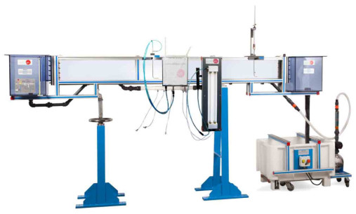
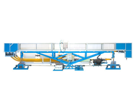
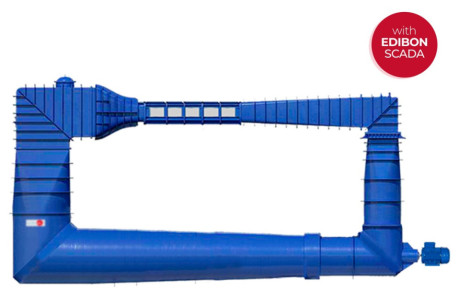
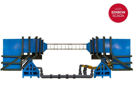
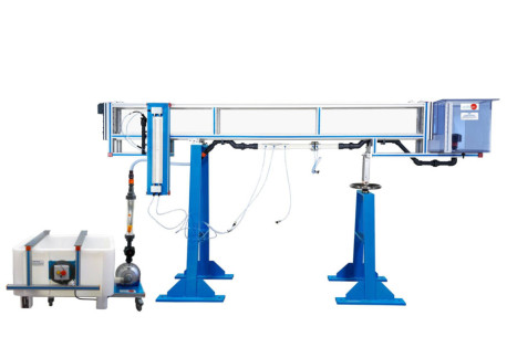
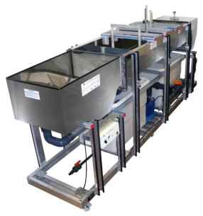
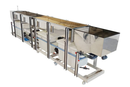
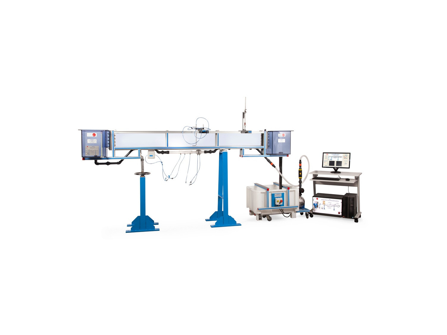
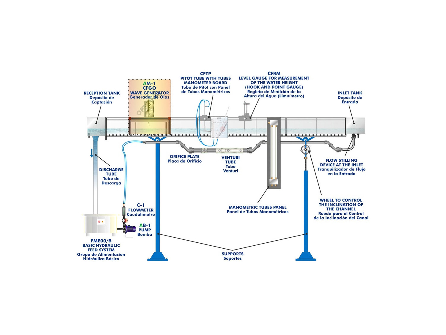
Channel, through which water flows, of rectangular section with transparent walls that enable to observe all the experiments. Water is taken from the storage tank by means of a hydraulic pump, with speed regulation, and, by the pipe, it is driven to the inlet tank, where there is a soothing of flow. After that, the water flows through the channel that discharges in the reception tank. Finally it comes back to the storage tank, completing the closed circuit.

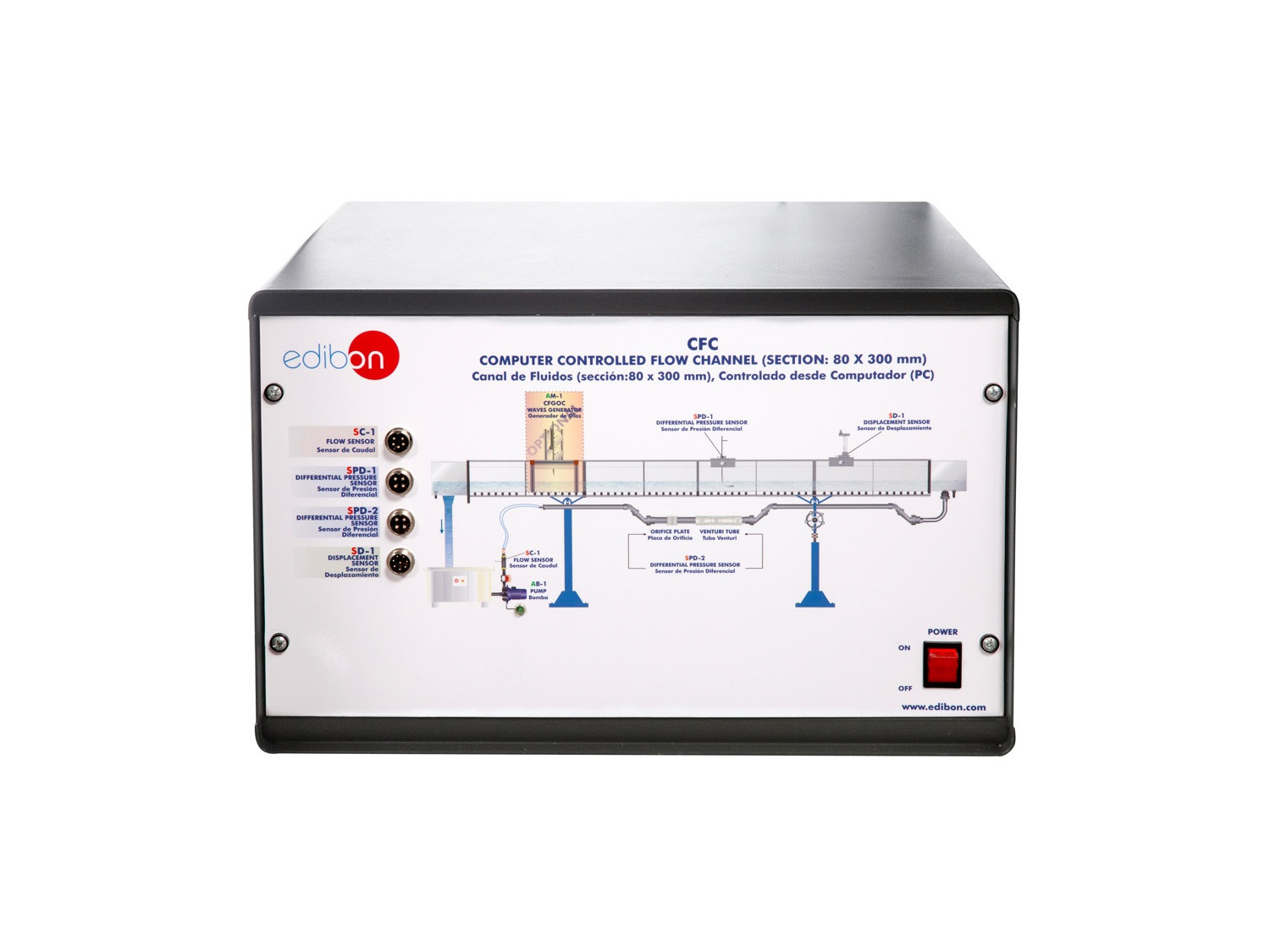
The unit includes the instrumentation and the suitable sensors (flow, pressure, etc.) to control and to measure the most representative parameters.

To regulate the flow through the channel, there is a valve at the output of the pump.

To measure the flow there is an orifice plate flow sensor and a Venturi type flow sensor. The flow also can be measured with the flow sensor of the Basic Hydraulic Feed System (FME00/B).

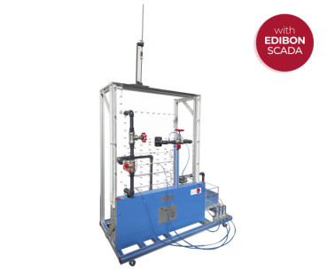
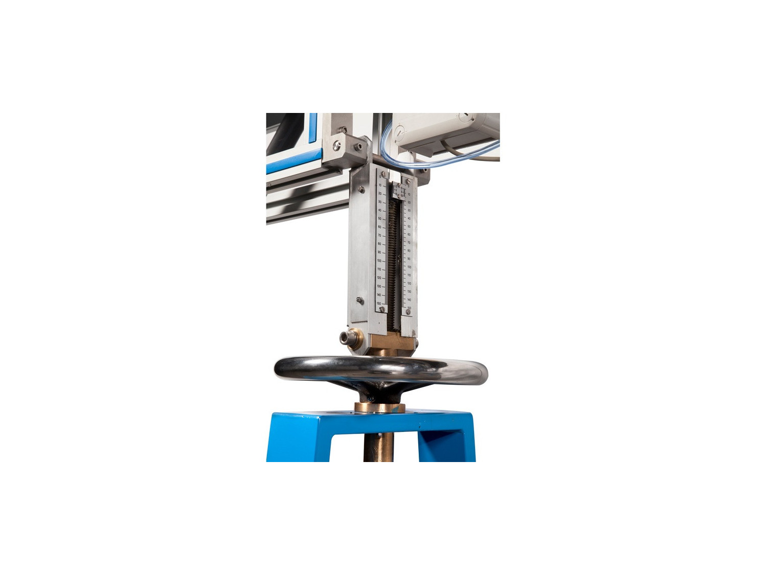
A limnimeter (CFRMC) is required to measure water level. Besides, a Pitot tube with tubes manometer board (CFTPC) us required to measure velocity/flow.

The channel is assembled on two supports, with a system to control the inclination of the channel.

There is a wide range of available accessories.

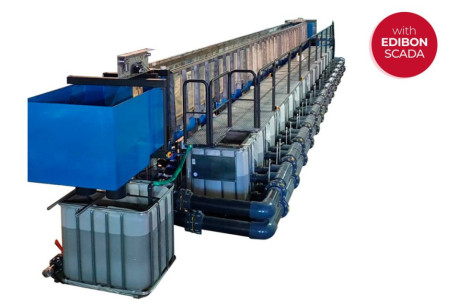
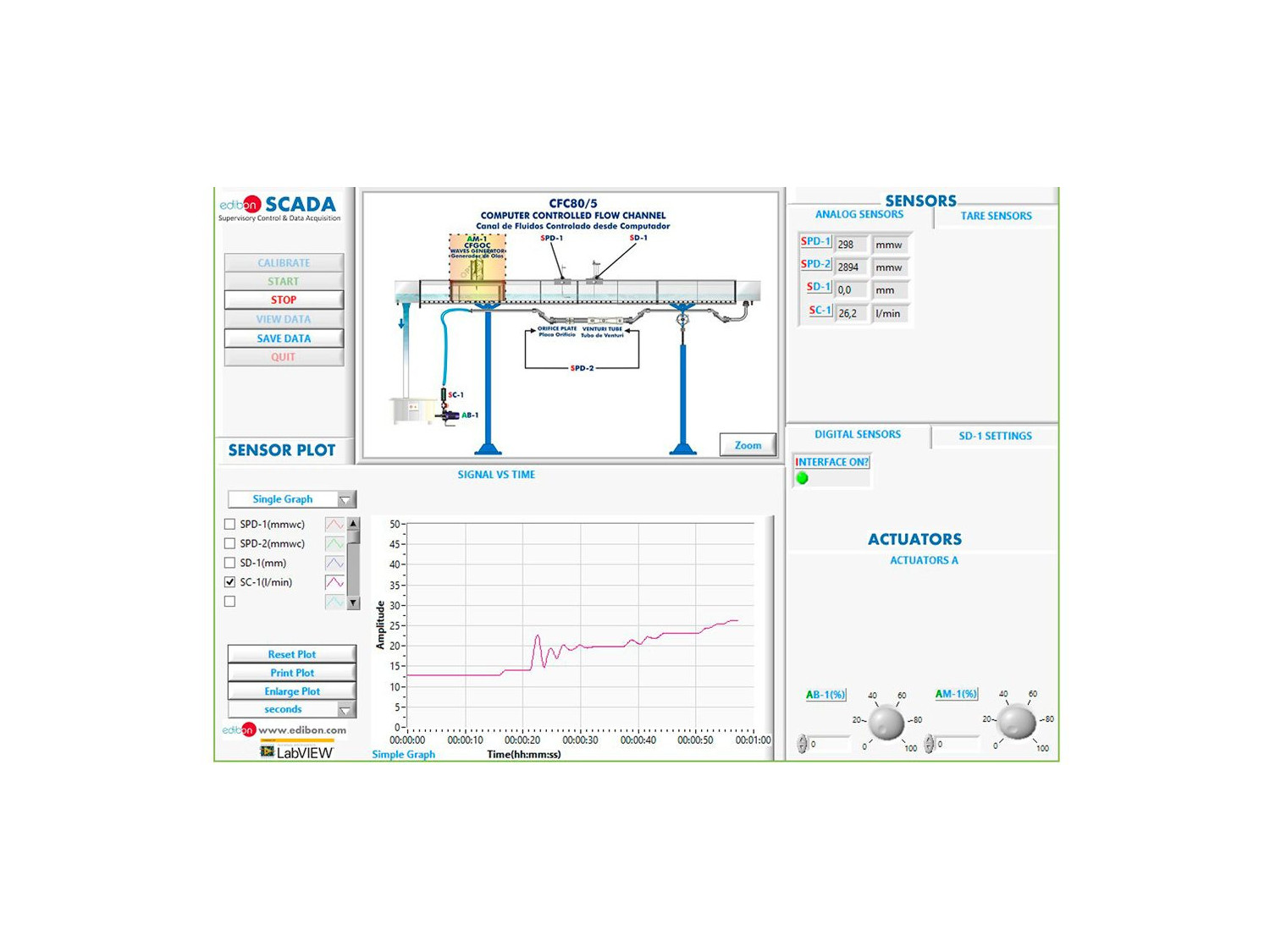
This Computer Controlled Unit is supplied with the EDIBON Computer Control System (SCADA), and includes: The unit itself + a Control Interface Box + a Data Acquisition Board + Computer Control, Data Acquisition and Data Management Software Packages, for controlling the process and all parameters involved in the process.

演習と指導の慣行

マニュアルに含まれるガイド付き実習

  1. Measurement of the water height and the velocity along the channel.
  2. Measurement of the flow with weirs of thin wall.
  3. Measurement of flow with changes in the channel section.
  4. Measurement of flow using Venturi flume.
  5. Control of the flow by gates.
  6. Level control using syphons.
  7. Flow on overflow dams.
  8. Flow among the pillars of a bridge.
  9. Connection of a channel to a culvert.
  10. Characterization of the hydraulic jump.
  11. Profiles of the water free surface.
  12. Investigation of flow and supercritical flow states.
  13. Measurement of water levels.
  14. Discharge processes on an underwater weir.
  15. Amount of energy in flows in open channels.
  16. Function of a syphon weir.
  17. Flow rate and drain coefficients of a syphon weir.
  18. Pipe flows.
  19. Comparison of overflow and syphon weirs.
  20. Observation of the throw of the water.
  21. Generation of different flow states by damming the down-stream water.
  22. Observation of the flow under an undershot weir: Observation of hydraulic motion on discharge.
  23. Relationship between dam height and discharge.
  24. Observation of discharges under a radial gate: Observation of hydraulic motion on discharge.
  25. Hydrostatic pressure on a weir.
  26. Investigations on waves.
  27. Behaviour of structures in rough sea.
  28. Applying and understanding Manning’s formula.
  29. Understanding sub- and super-critical flow.
  30. Learning how to apply force-momentum and steady flow energy equations to simple flow situations.
  31. Investigation of the transition from running to shooting flow.
  32. Sensors calibration.

より実用的な練習をして、ユニットを完成させる

  1. Filling of the Pitot tube.
  2. Filling of the venturi meter with analog output.
  3. Calculation of water flow.
  4. Use of level gauge for measurement of the water height.
  5. Flow visualization.

Other possibilities to be done with this Unit:

  1. Many students view results simultaneously. To view all results in real time in the classroom by means of a projector or an electronic whiteboard.
  2. Open Control, Multicontrol and Real Time Control. This unit allows intrinsically and/or extrinsically to change the span, gains, proportional, integral, derivative parameters, etc, in real time.
  3. The Computer Control System with SCADA and PID Control allow a real industrial simulation.
  4. This unit is totally safe as uses mechanical, electrical and electronic, and software safety devices.
  5. This unit can be used for doing applied research.
  6. This unit can be used for giving training courses to Industries even to other Technical Education Institutions.
  7. Control of the CFC unit process through the control interface box without the computer.
  8. Visualization of all the sensors values used in the CFC unit process.
  9. By using PLC-PI additional 19 more exercises can be done.
  10. Several other exercises can be done and designed by the user.

品質

アフターサービス

リクエスト情報