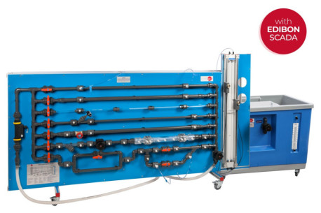
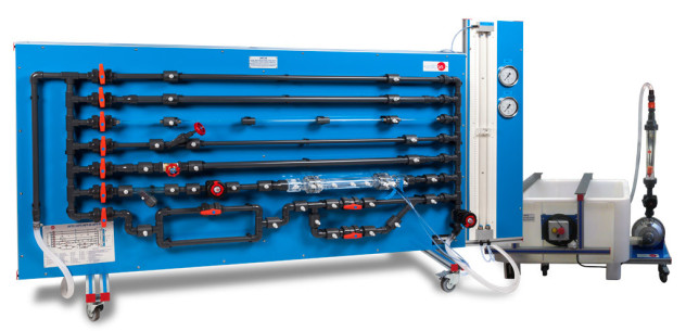
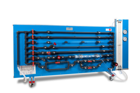
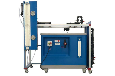
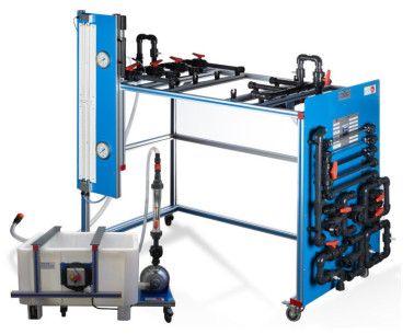
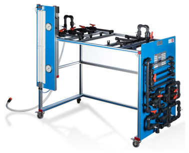
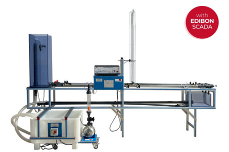
The Computer Controlled Air Ventilation and Conditioning Unit, "TEVC", designed by EDIBON, has been conceived for the comprehensive study of ventilation, filtration, and air distribution processes in duct systems. This unit accurately reproduces the operation of an Air Handling Unit (AHU), allowing the analysis of airflow behavior, pressure losses, branch balancing, and the system’s response under different network configurations and operating conditions.
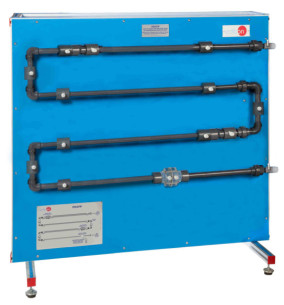
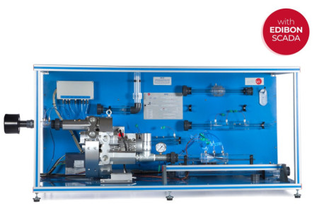
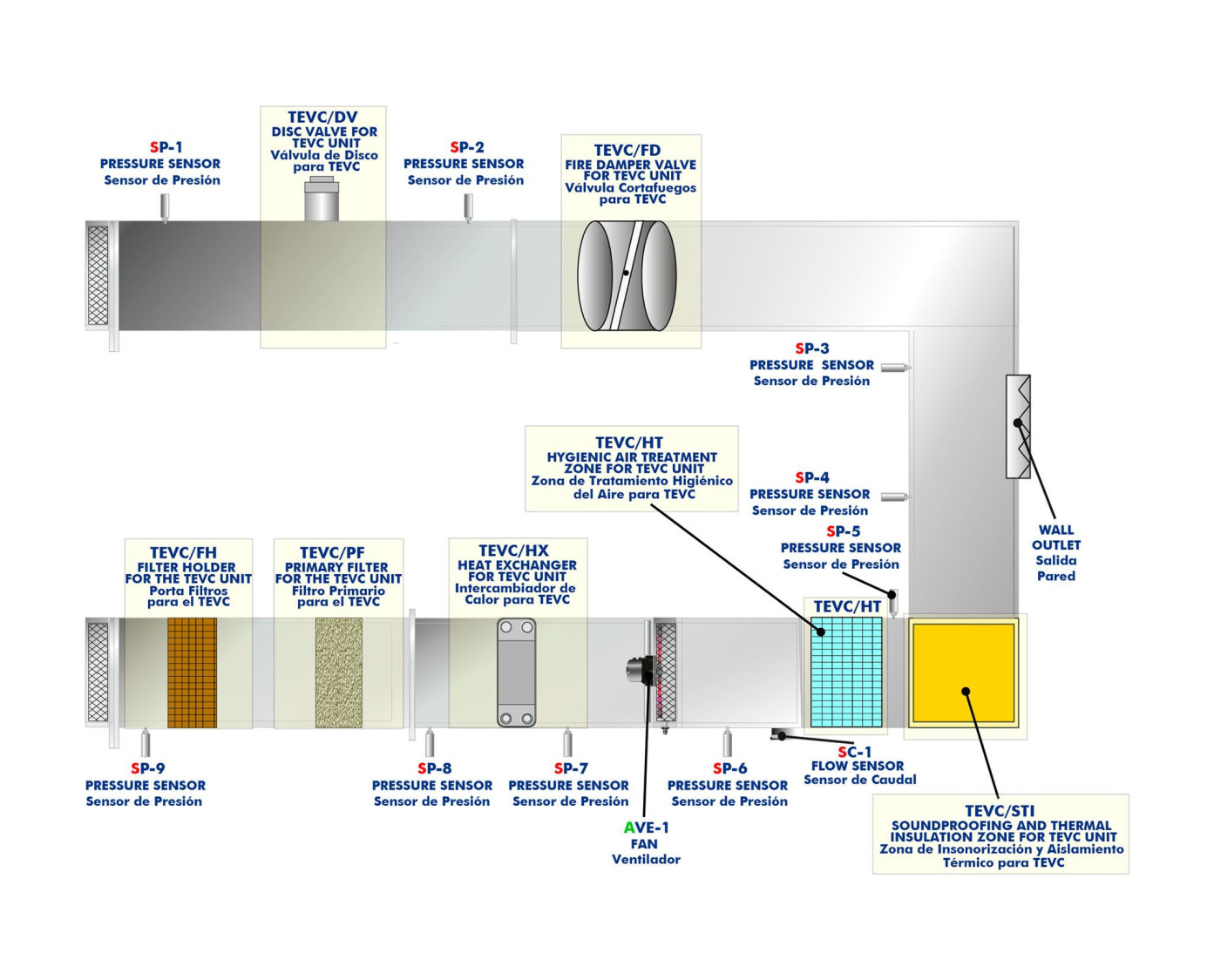
Air is drawn into the system through a rectangular inlet with filter holder, where primary filtration removes suspended particles before entering the fan. A variable-speed centrifugal fan, controlled via software, then drives the air through the main circuit, generating adjustable flow rates and distributing it through a metal duct system. This system, which includes filtering elements, branch connections, and adjustable air outlets, enables the study of the influence of each component on flow distribution and pressure variations along the network.
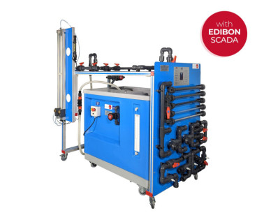
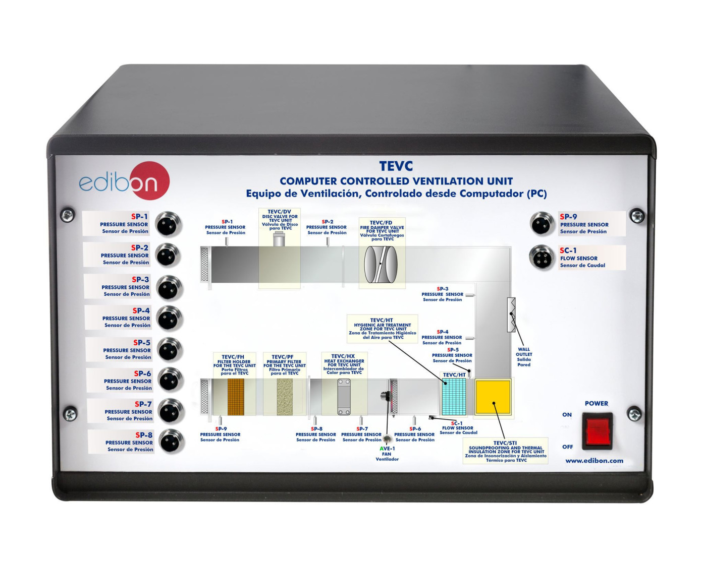
The "TEVC" includes a complete instrumentation system composed of pressure sensors, flow sensors, and air velocity sensors, allowing the representation of pressure and velocity profiles throughout the installation as well as the calculation of the actual volumetric flow according to the operating conditions. Measurements are recorded and analyzed in real time through the control software, enabling the quantitative evaluation of ventilation phenomena and the experimental study of the conservation of mass and energy principles within the airflow.
Thus, the "TEVC" provides an advanced tool for training and applied research in air ventilation and conditioning, offering a realistic and controlled representation of an AHU’s operation and the effects of its variables on the overall system performance.
Additional recommended elements (Not included):
- TEVC/FH. Filter Holder for the TEVC Unit: The Filter Holder for the TEVC Unit, "TEVC/FH", is a component for housing panel filters at the inlet of the ventilation system. Its structure ensures stable and airtight installation, allowing pre-filters of different efficiencies to be integrated according to the test requirements.
- The "TEVC/FH" facilitates the assembly and replacement of filter elements and allows the effect of initial air filtration on pressure drop and the overall performance of the ventilation system to be studied.
- TEVC/PF. Primary Filter for the TEVC Unit: The Primary Filter for the TEVC Unit, "TEVC/PF", is a filtration element designed to retain suspended particles before the air is blown into the system. It is located at the entrance to the ventilation system and after the "TEVC/FH," if requested. It consists of a filter with a large effective surface area mounted on a frame, which ensures low initial pressure drop and a long service life.
- The "TEVC/PF" allows the effect of primary filtration on air quality and system pressure losses to be studied, as well as comparing the performance of the equipment with and without filtration installed.
- TEVC/HT. Hygienic Air Treatment Zone for TEVC Unit: The Hygienic Air Treatment Zone for TEVC Unit, "TEVC/HT", consists of a compact high-efficiency filter designed to reduce the presence of biological particles and improve the quality of the air supplied. It is located behind the fan and its filter medium limits the growth of microorganisms and is particularly suitable for applications where enhanced hygienic control is required.
- The "TEVC/HT" allows the impact of advanced air treatment on pressure drop, flow rate, and overall ventilation system performance to be studied, replicating the practices used in installations with demanding environmental requirements.
- TEVC/STI. Soundproofing and Thermal Insulation Zone for TEVC Unit: The Soundproofing and Thermal Insulation Zone for TEVC Unit, "TEVC/STI", is a set of soundproofing and thermal insulation filters made of rock wool with finishes to improve thermal and acoustic protection. It is located before the wall outlet.
- The "TEVC/STI" reduces the noise level generated by the fan and limits heat loss, allowing the performance of the system with and without insulation to be compared. Its direct installation on the duct provides a realistic example of the solutions used in installations to improve energy efficiency and acoustic comfort.
- TEVC/DV. Disc Valve for TEVC Unit: The Disc Valve for TEVC Unit, "TEVC/DV", consists of an adjustable drive terminal that is installed at the ends of the duct system branches, in this particular case, at the end of the run. Its adjustable central part allows the flow opening to be modified, controlling the air flow supplied and generating different pressure drops depending on its position.
- The "TEVC/DV" allows for practical study of flow regulation, balancing of networks with parallel branches, and the influence of terminals on air pressure and velocity within a ventilation installation.
- TEVC/FD. Fire Damper Valve for TEVC Unit: The Fire Damper Valve for TEVC Unit, "TEVC/FD", consists of a safety gate installed in the duct to reproduce the actual sectorization systems used in installations. It is located behind the wall outlet and its tilting part closes automatically by means of a thermal mechanism, blocking the passage of air and simulating the function of protection against the spread of fire.
- The "TEVC/FD" allows the analysis of pressure drop, the effect on flow distribution, and the behavior of safety elements present in real ventilation networks.
- TEVC/HX. Heat Exchanger for TEVC Unit: The Heat Exchanger for TEVC Unit, "TEVC/HX", consists of an air-water coil that allows the air in the duct to be heated or cooled by connecting to an external hot or cold water circuit. The thermal treatment modifies the temperature of the air being blown and allows its effect on the flow, pressure, and distribution of air in the network to be observed.
- The "TEVC/HX" is installed before the fan, so that the fan draws in thermally treated air, ensuring stable flow, more uniform transfer, and avoiding the risk of condensation in the impeller. In addition, temperature sensors are included to monitor the process and facilitate control and analysis of the system’s thermal behavior.
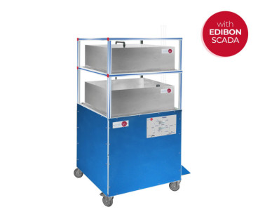
This Computer Controlled Unit is supplied with the EDIBON Computer Control System (SCADA), and includes: The unit itself + a Control Interface Box + a Data Acquisition Board + Computer Control, Data Acquisition and Data Management Software Packages, for controlling the process and all parameters involved in the process.
 クッキーの設定


 カタログ
カタログ
 コンテストの仕様


