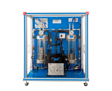
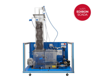
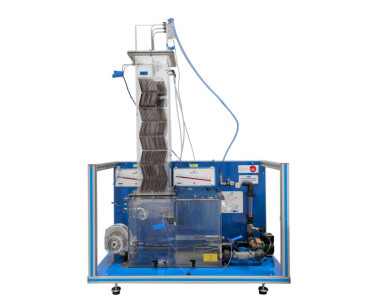
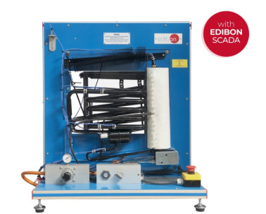
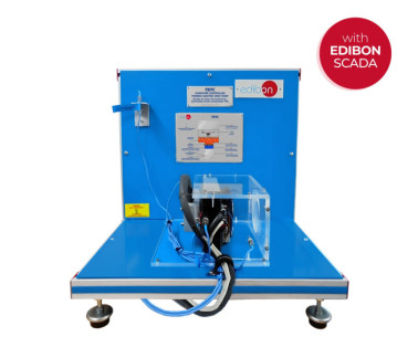
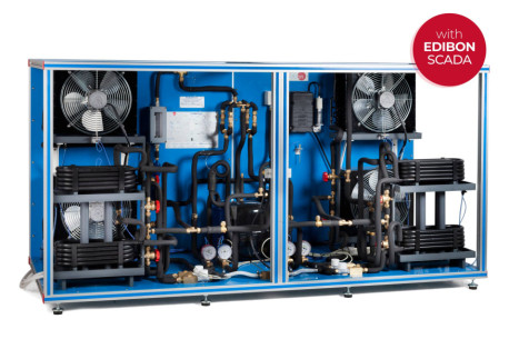
The Computer Controlled Refrigeration Cycle Demonstration Unit, "TCRC", designed by EDIBON, allows the demonstration of vapour compression refrigeration and heat pump cycle with visual observation of all important processes.
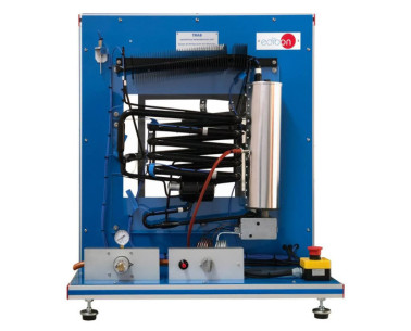
Thanks by utilising a non-toxic refrigerant fluid with a low vapour pressure (NE30-Fluid 0z36 refrigerant, environmental friendly), the evaporation and condensation processes are clearly visible in the glass cylinders (evaporator and condenser).
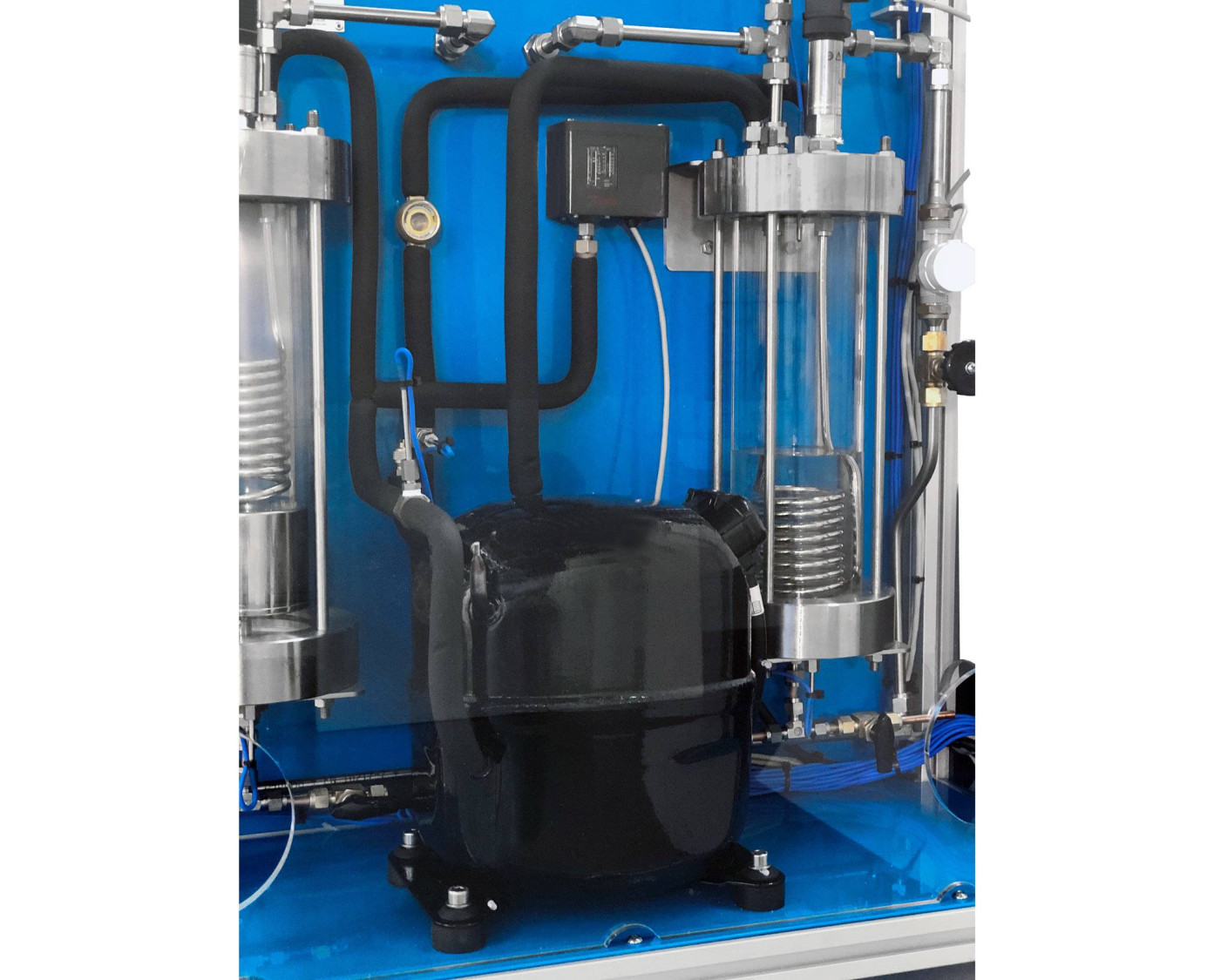
The evaporator is a vertical cylinder, made of glass, containing NE30-Fluid 0z36, closed on both ends. Into the glass cylinder there is a niquel-plated copper coil.
Hermetic compressor draws vapour from the evaporator and compresses this before discharging it to the condenser. The low pressure of the evaporator causes the refrigerant to boil. The water flowing through the coil heats the refrigerant causing the vapours generation and the water temperature decreases.
From the compressor the high pressure vapour passes to the condenser.
The condenser, as the evaporator, is a glass recipient closed on both ends with a nickel-plated copper coil into it. Vapour condenses on the surface of the coil and falls to the bottom of the condenser. The liberated heat by the refrigerant phase change is transferred to the cooling water flowing through the coil.
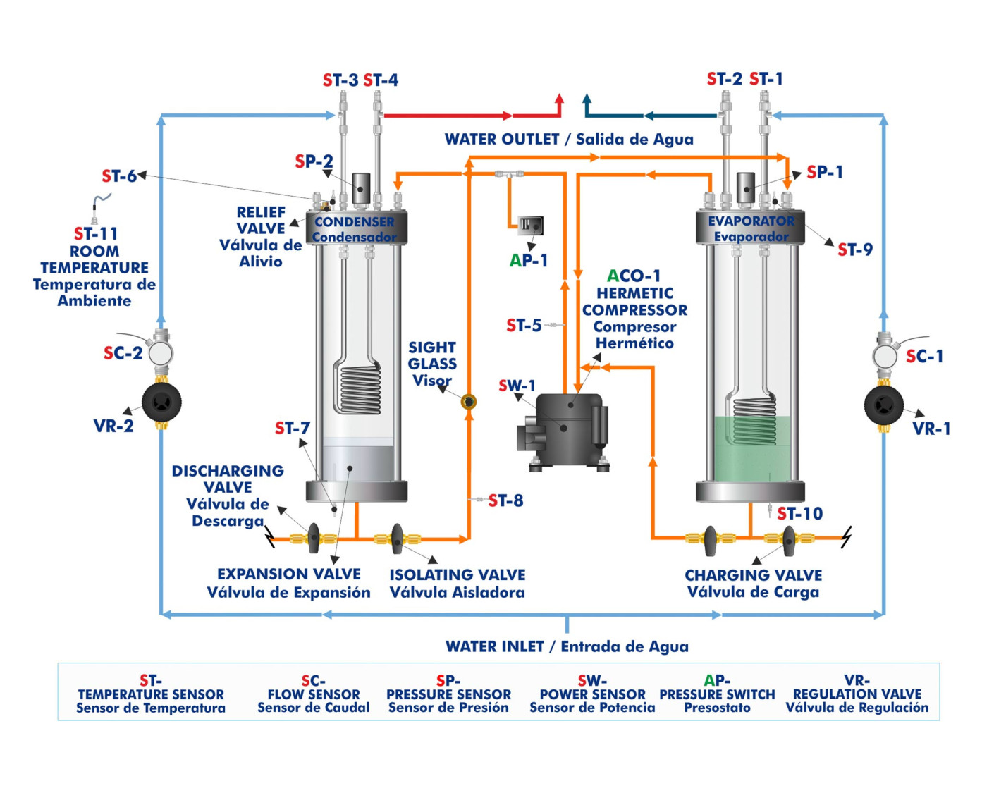
The float valve located at the base of the condenser, that works as an expansion valve, controls the flow of high pressure refrigerant liquid returning to the evaporator. The refrigerant, after passing through the floating valve, expands to form a liquid vapour mixture at the same pressure as the evaporator and the cycle is repeated.
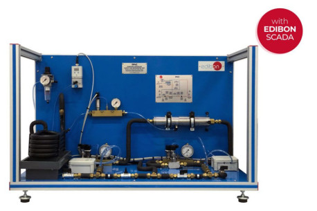
Besides, an insulating valve is installed in the condenser inferior part that can be closed for the demonstration of the technique used in the maintenance of refrigeration installations, whether commercial or industrial, where the refrigerant is collected and stored in the condenser. This technique is important for demonstrating how to prevent a possible refrigerant gas leak during the maintenance operations.
The unit allows a safe operation since it includes different safety elements, such as a high pressure switch that turns off the compressor when the pressure in the condenser and at the condenser upper part, the unit has a relief valve that opens itself when the condenser pressure is higher than the maximum valve allowed.
By adjustment of the water flow to the evaporator and condenser coils, using control valves, the condensing and evaporating pressures can be varied.
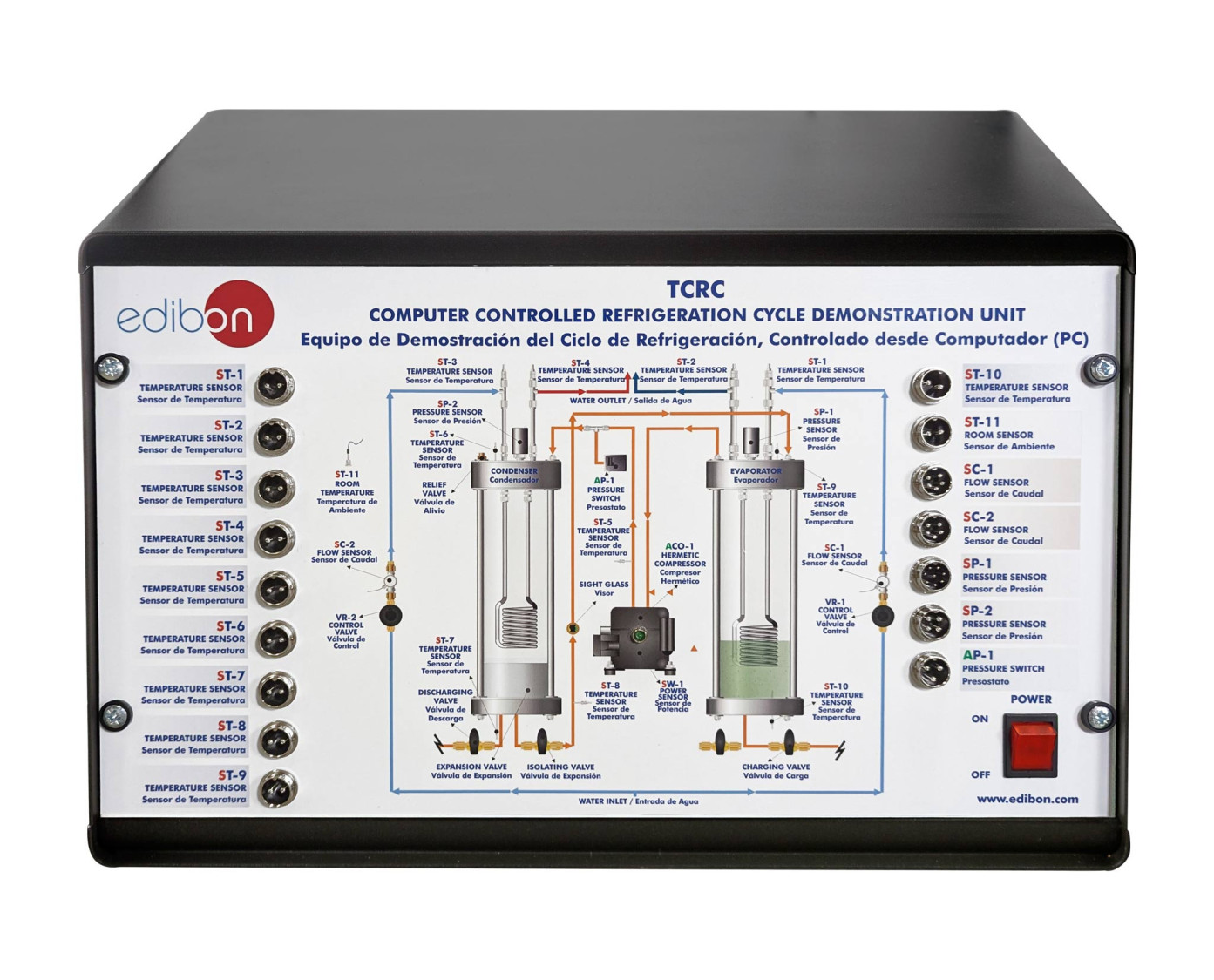
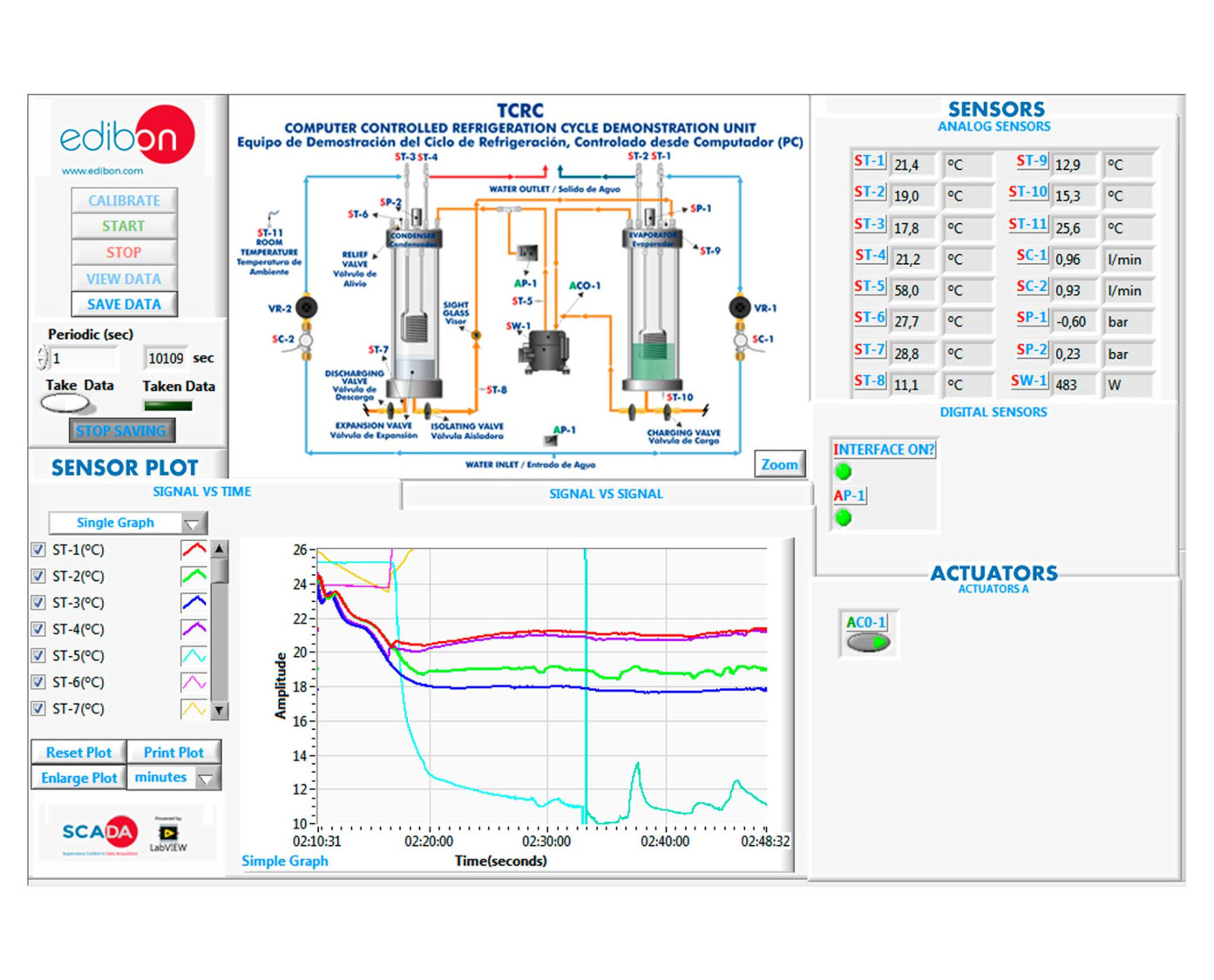
We can control the unit and know, at any time, the measure of:
- The temperature and pressure of the refrigerant fluid in the evaporator and in the condenser.
- The temperature of the compression and expansion processes.
- The temperature of the water inlet and outlet at the coils of the evaporator and condenser.
- The water flow in the two coils.
- The room temperature.
- The electrical power used in the compression stage, etc.
This Computer Controlled Unit is supplied with the EDIBON Computer Control System (SCADA), and includes: The unit itself + a Control Interface Box + a Data Acquisition Board + Computer Control, Data Acquisition and Data Management Software Packages, for controlling the process and all parameters involved in the process.
 Cookies首选项


 目錄
目錄
 比赛规格
比赛规格


