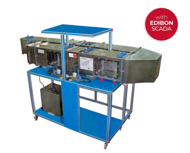
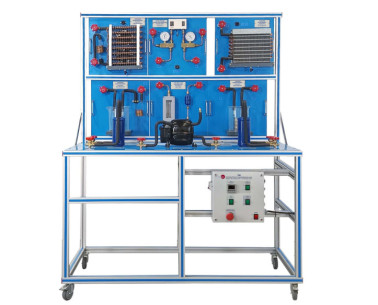
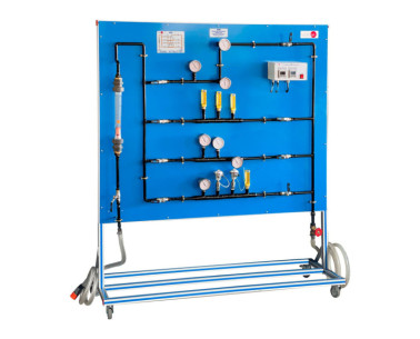
TRAMC/1 Home refrigeration model

HOME REFRIGERATION MODEL - TRAMC/1

革新的なシステム

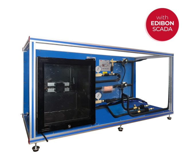
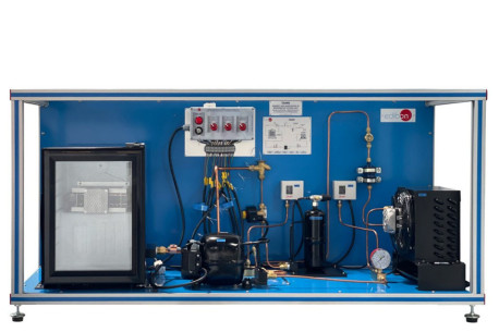
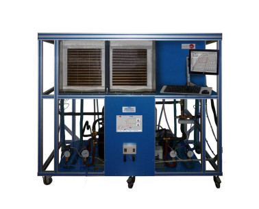
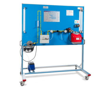
It consists of a refrigeration chamber with heater as refrigeration load, evaporator, fan and two expansion elements, capillary tube or expansion valve, selected by a solenoid valve.

一般的な説明を表示

概要

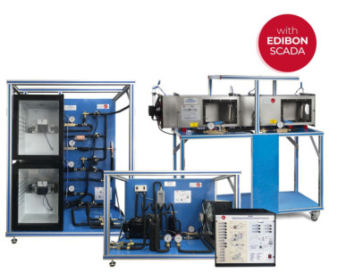
The minimum supply consists of two main elements: the TRAMC Unit Base, "TRAMC-UB", and at least one of the required elements described below.

The models are interconnected by special refrigerant hoses.

The main components of the TRAMC Unit Base, "TRAMC-UB", are compressor, condenser, refrigerant receiver and accessories to complement the refrigeration cycle. They are arranged in a clear and visible way to facilitate the understanding of the thermodynamic cycle.

The SCADA software, developed by EDIBON, has a data acquisition and control system that enables to automate the unit and to perform and assess all the practical exercises quickly, as well as to represent all the measured and calculated magnitudes in real time.

The measurements of the experiment are recorded in function of time and the generation of file compatible with spreadsheet applications via software. The temperatures and pressures existing in the system are recorded by sensors. Besides, the thermodynamic cycle can be represented in p-H and H- X diagrams.

It consists of a refrigeration chamber with heater as refrigeration load, evaporator, fan and two expansion elements, capillary tube or expansion valve, selected by a solenoid valve.

This Computer Controlled Unit is supplied with the EDIBON Computer Control System (SCADA), and includes: The TRAMC Unit Base (TRAMC-UB) + a Control Interface Box + a Data Acquisition Board + Computer Control, Data Acquisition and Data Management Software Packages, for controlling the process and all parameters involved in the process.

演習と指導の慣行

マニュアルに含まれるガイド付き実習

  1. Function and behavior of the refrigeration circuit components.
  2. Study and comparation of work with different expansion elements:
  • Expansion valve.
  • Capillary tube.
  1. Representation of the thermodynamic cycle in the p-h log diagram.

より実用的な練習をして、ユニットを完成させる

  1. Sensors calibration.
  2. Properties of the refrigerant R-513a.
  3. Enthalpy-pressure diagram for the refrigerant R-513a.

利用可能な類似の機器

品質

アフターサービス

リクエスト情報