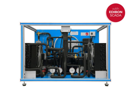
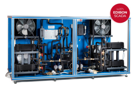
The Heat Pump + Air Conditioning + Refrigeration with 2 Condensers and 2 Evaporators (Water/Air), "THAR22B", designed by EDIBON, has as aim introduce the student to the study of the heat pumps, air conditioning and refrigeration, as well as the analysis and determination of the operation typical parameters of the unit depending on the two types of fluids used in the processes of evaporation and condensation (air and water).
This unit can have different applications, depending on the type of cold focus or hot focus used in the processes of evaporation andcondensation. This unit consists of the following stages:
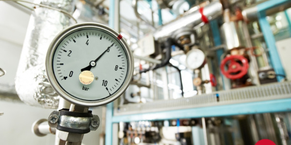
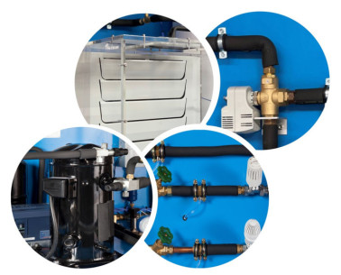
- Compression: This stage begins when the coolant enters to the compressor. This coolant iscompressed, increasing its pressure and temperature. To measure these variables theunit includes a manometer and a temperature sensor.
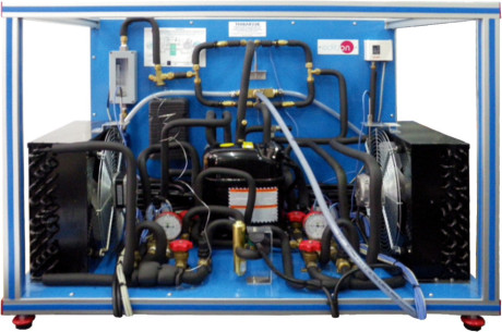
- Condensation: The coolant has two possibilities: divert the coolant through the air condenser, or through the water condenser. The coolanttransfers its heat to the water (or to the air) that flows for the condenser. At the end of this stage, the pressure and the temperatureof the coolant are measured by means of a manometer and a temperature sensor.
- Expansion: The coolant circulates through an accumulator and a filter, to retain particles of condensate, and a flow meter. Next it circulatesthrough the valve of expansion, which causes a fall of pressure and temperature of the coolant. At the end of this stage, the pressureand the temperature of the coolant are measured by means of a manometer and temperature sensor.
- Evaporation: The coolant has two possibilities: divert the coolant through the air evaporator, or through the water evaporator. The coolant absorbs the heat of the water (or the air) that flows for the evaporator. At the end of this stage, the pressure and the temperature of the coolant are measured by means of manometer and a temperature sensor. Finally, the coolant circulates through a liquid separator to retain liquid particles before going on to the compressor.
The condensers and evaporators have different meters for the measure of the most important parameters (temperatures and flows). Inaddition, the unit includes a high pressure control to avoid an excess of pressure in the unit.
 クッキーの設定
 - THAR22B")
 カタログ
カタログ
 コンテストの仕様


 - THAR22B")