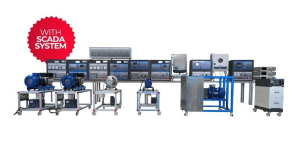
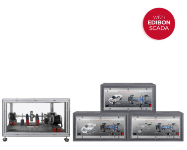
The Computer Controlled Hybrid and Electric Vehicles Application, "AEL-EHVC", hhas been developed by EDIBON to facilitate the understanding and analysis of key technologies used in electric and hybrid vehicles within the context of modern electric mobility.
Given the wide diversity of electric and hybrid vehicle configurations that can be studied, this application has been developed with a modular design, allowing users, students, or researchers to implement the desired vehicle topology. This feature offers a competitive advantage over other systems on the market by enabling real comparisons between different configurations in terms of operation, efficiency, and dynamic behavior.
The "AEL-EHVC" application is structured into three main areas of study:
- 100% Electric Vehicle (included): Comprising a set of modules that allow for the study of a fully electric vehicle’s behavior, including the traction motor, terrain simulator, frequency inverter, and regenerative DC power source.
- Hybrid Vehicle (recommended) (Not included): Incorporates a servomotor with a magnetic clutch, capable of replicating the behavior of a gasoline engine interacting with the main electric motor.
- Electric Vehicle Charging Station (recommended) (Not included): A real charging system identical to those used at service stations, enabling the study of the electric vehicle charging process.
Given the high potential of this application, the following sections detail the two vehicle topologies that can be configured, along with the capabilities of the included SCADA supervision and control software:
Elements included:
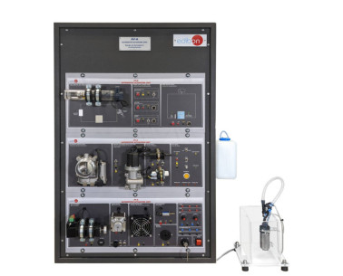
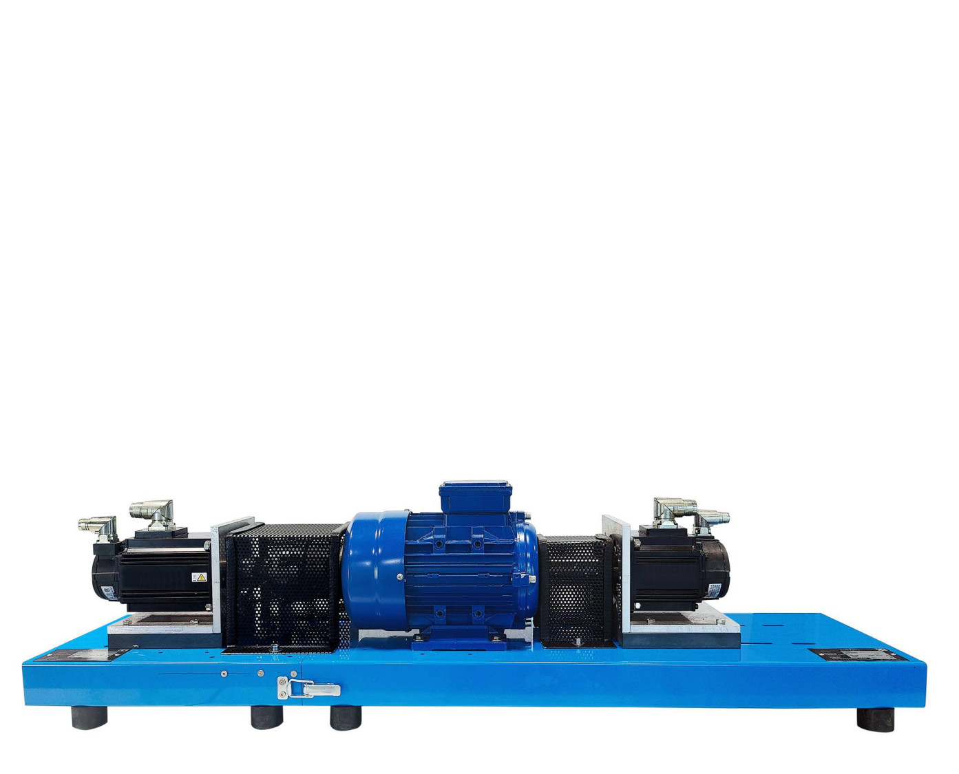
The 100% Electric Vehicle Topology integrates all the elements necessary to simulate a real electric vehicle:
- N-DCPWS/R. Regenerative DC Power Supply Module: Simulates the behavior of the traction battery.
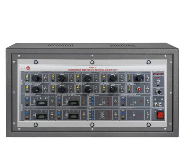
- N-RGTR. Regenerative Powertrain Module: Regulates the speed and torque of the electric motor.
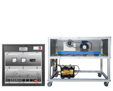
- EMT7B/1K-E. 3PH Squirrel-Cage Industrial Motor, 1 kW, 4 Poles: Emulates the main traction system.
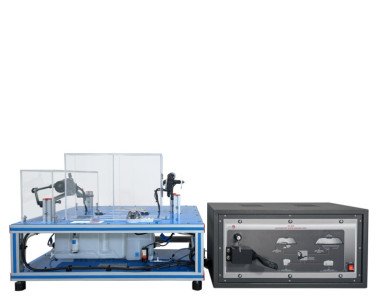
- Terrain Simulation Servomotor: Coupled to the motor shaft, allows the simulation of uphill, downhill, and flat terrain conditions.
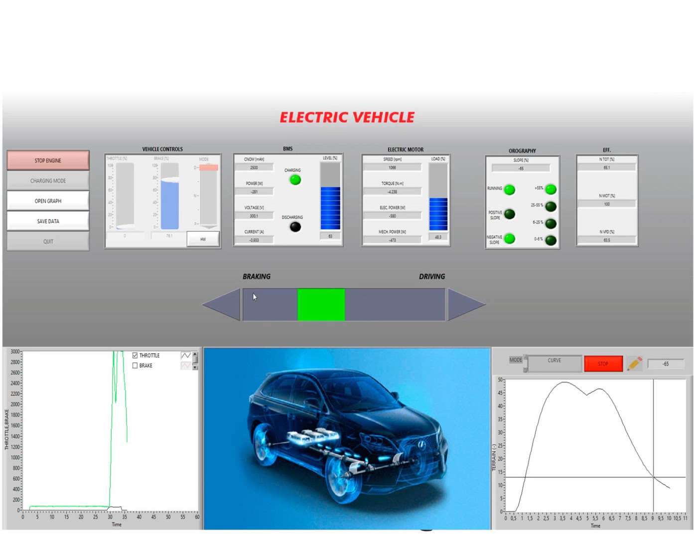
By simulating different slopes, users can observe the principles of energy conversion between electrical and mechanical forms, both in traction (uphill) and regeneration (downhill) modes.
The system also includes a set of real automotive pedals (accelerator and brake), allowing practical management of acceleration, deceleration, and regenerative braking phases.
The powerful SCADA software stands out, enabling the modeling of different types of batteries by configuring key parameters such as:
- Capacity in ampere-hours (Ah).
- Charging voltages for bulk, absorption, and float stages.
The user can analyze the power flow during charging and discharging in a virtual energy buffer, safely replicating the behavior of a real lithium battery across the different charging stages.
Additional recommended elements (Not included):
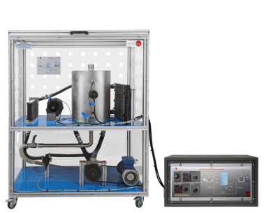
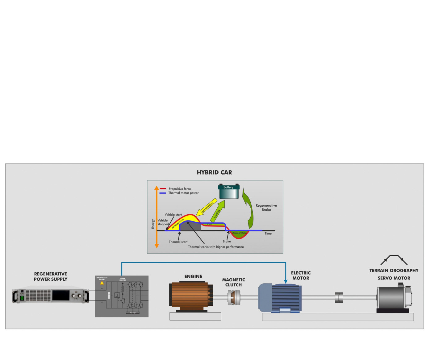
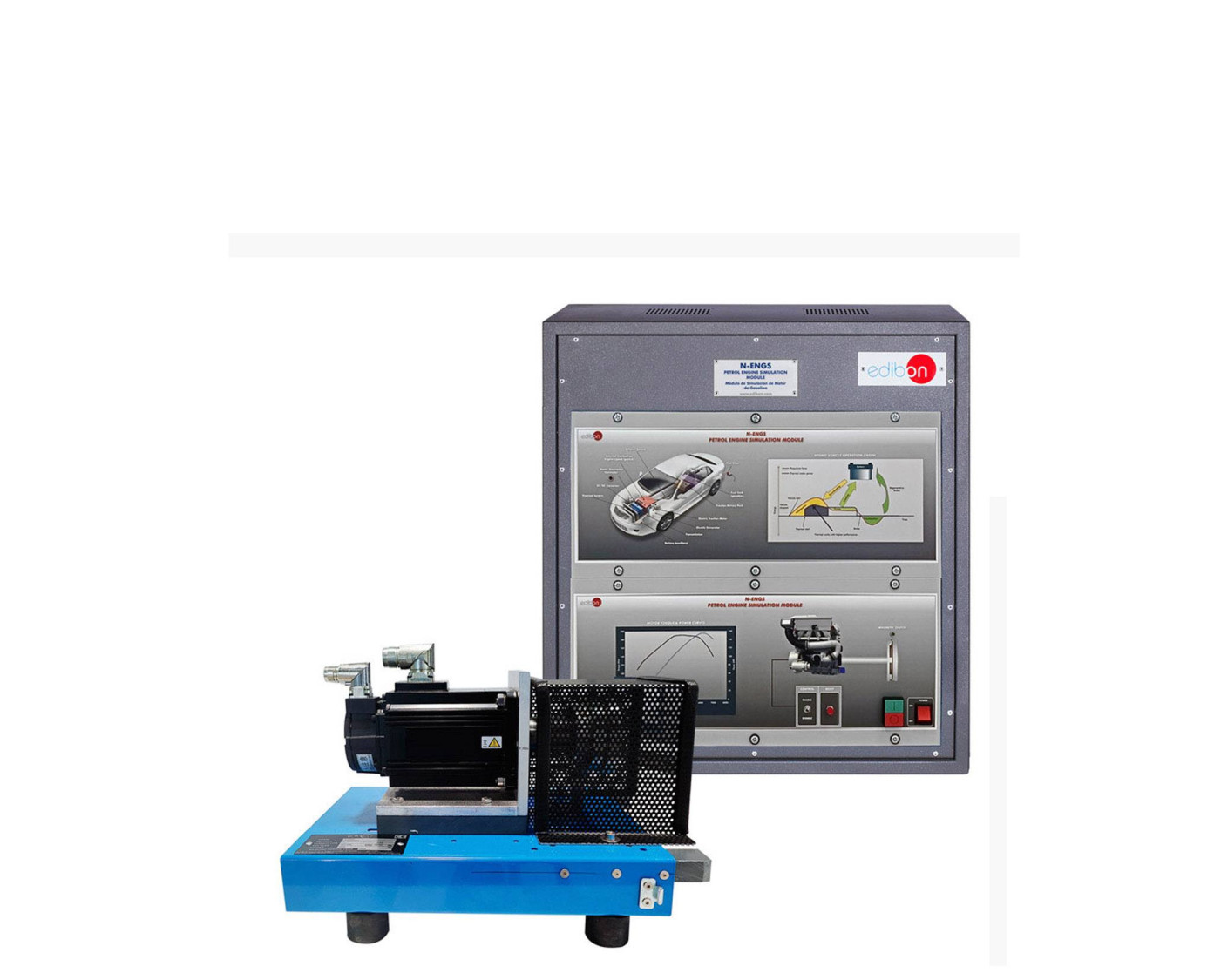
The hybrid vehicle topology extends the previous capabilities by incorporating an additional servomotor that simulates the behavior of a gasoline engine.
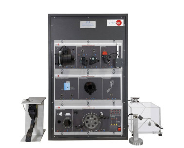
N-ENGS. Petrol Engine Simulation Module.
Thanks to a magnetic clutch, the thermal engine can be coupled or decoupled from the electric traction train in a controlled manner, depending on the vehicle’s operating regime:
- At low revolutions, the vehicle operates purely in electric mode.
- When exceeding a certain speed threshold, the gasoline engine smoothly couples to the electric motor, replicating a hybrid traction mode.
In this phase, the electric motor acts as an assistant, providing extra power only when requested by the accelerator.
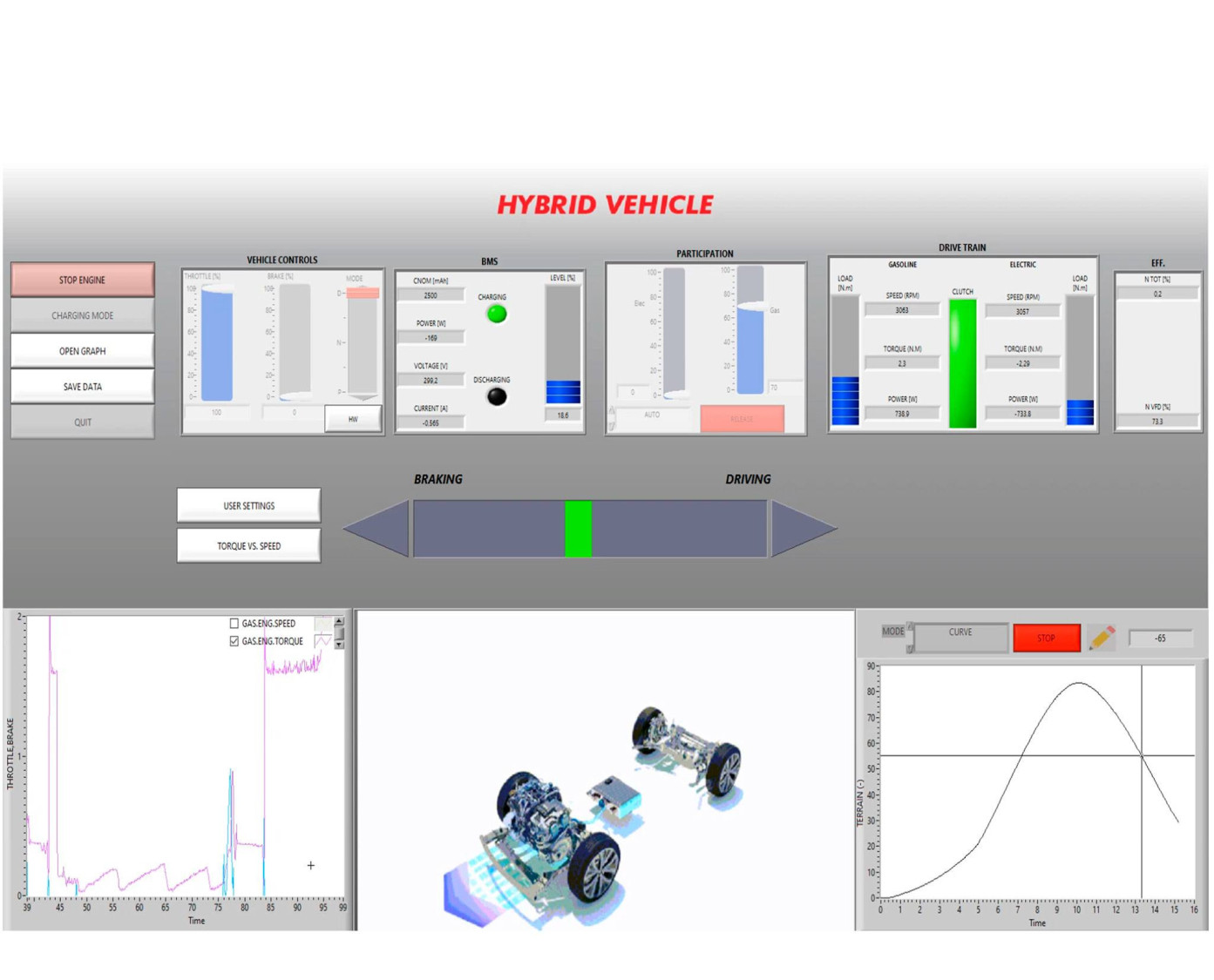
The SCADA system plays a key role in dynamically configuring this topology, allowing users to:
- Define the degree of assistance provided by the electric motor to the combustion engine.
- Program the torque/speed curve of the gasoline engine by adjusting parameters such as starting torque, maximum torque, and torque at maximum speed.
These advanced options allow users to experiment with different control strategies, as if reprogramming the ECU of a real hybrid vehicle, greatly varying the dynamic behavior of the system.
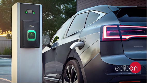
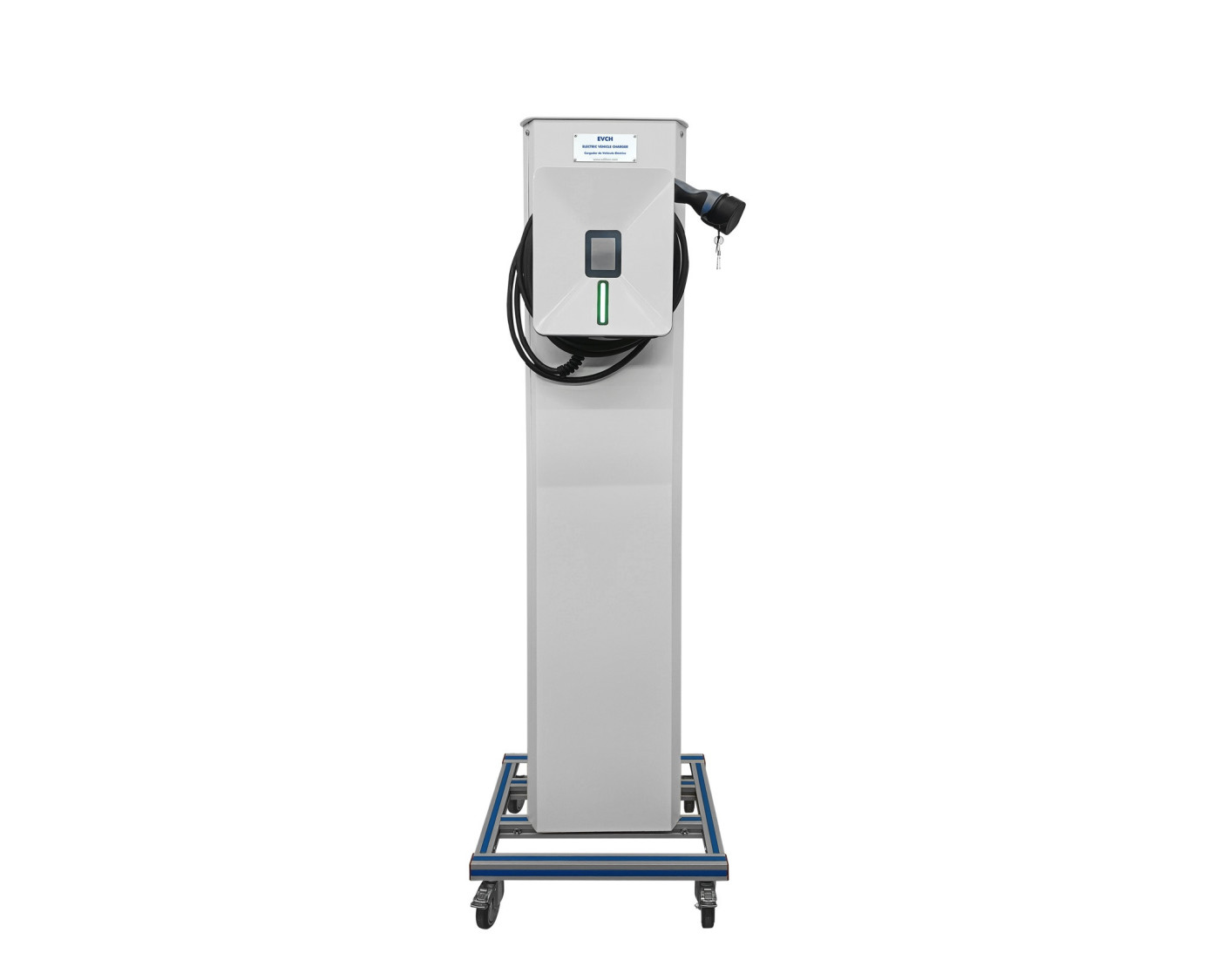
EVCH. Electric Vehicle Charger.
Optionally, the "AEL-EHVC" application can be complemented with a real electric vehicle charging module, identical to those used in service stations.
This device enables users to:
- Familiarize themselves with electric vehicle charging protocols.
- Monitor energy flows during the charging process.
- Analyze the relationship between the previously defined battery capacity and the required charging time.
From the SCADA system, users can:
- Enable and disable battery charging remotely.
- Monitor real-time electrical parameters (voltage, current, power).
- Study how the battery’s state of charge evolves throughout the charging cycle.
This module provides a deep understanding of one of the critical factors in electric mobility: how battery size and charger type directly influence charging times.
This Computer Controlled Unit is supplied with the EDIBON Computer Control System (SCADA), and includes: The unit itself + Computer Control, Data Acquisition and Data Management Software Packages, for controlling the process and all parameters involved in the process.
 クッキーの設定


 カタログ
カタログ
 コンテストの仕様


