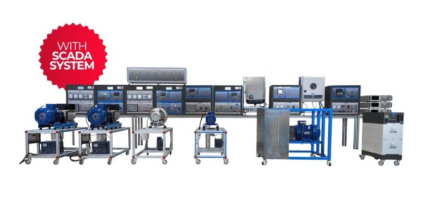
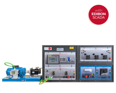
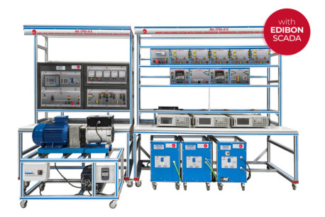
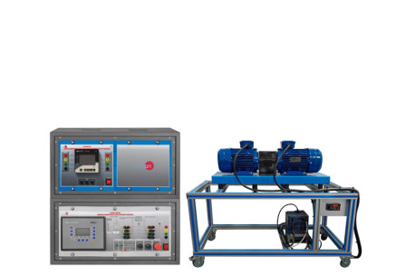
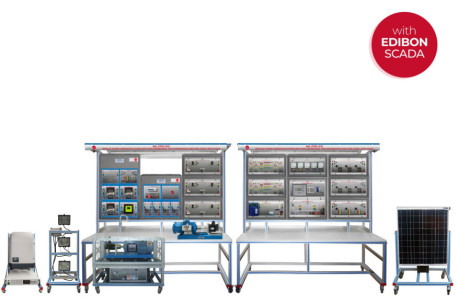
The High Power Synchronous Generators Application, "AEL-HPSG", has been designed by EDIBON to study the procedure and the maneuvers required for the synchronization of synchronous generators with the grid, with the aim of delivering the generated energy as done in actual power plants.
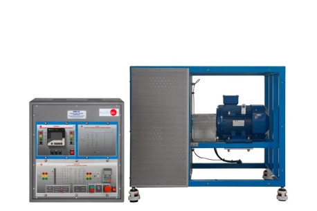
The "AEL-HPSG" application allows the user to go deeper into the working principles and control of synchronous generators to show the step-by-step synchronization process with the electrical grid. For this, the application includes a synchronous generator coupled to a motor (which will act as driving force, simulating a turbine) along with a series of modules such as a single-phase transformer, an AC/DC converter and a voltage regulator which form the generator excitation circuit. It is also included an analog overcurrent relay as grid protection device and a network analyzer to monitor the generation electrical parameters such as the active and reactive powers generated, frequency, voltage, current, power factor, etc.
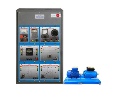
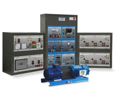
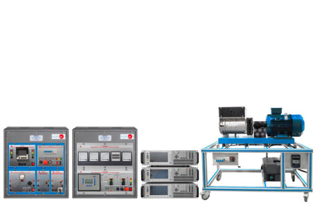
This application offers two possibilities regarding the generation group control. The first option, the manual control of synchronous generators kit, includes modules for the motor speed control (turbine) and a PWM signal generator module for the control of the synchronous generator excitation current (and therefore the output voltage). This enables the user to carry out the no load, under load and short circuit test aimed to obtain the characteristic curves and the equivalent circuit of the synchronous generator. This kit also includes a synchronization module which will allow the user to monitor and carry out manually the synchronization process. For that, the synchronization module has two analog voltmeters (grid and generation voltage), two frequency meters (grid and generator frequency), a digital synchroscope and two push-buttons for closing and opening the synchronization switch.
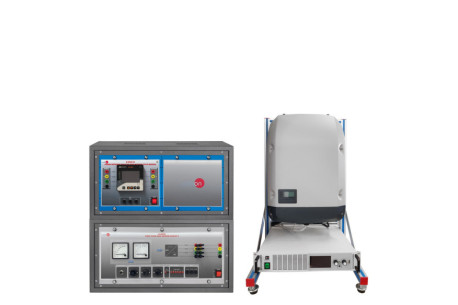
The second option, the synchronous generator automatic control module, offers the possibility to control automatically every electrical and mechanical parameters of the generator-turbine group. The most signifcant control parameters are the turbine speed, the generator frequency, the excitation current, the voltage at the generator output and the active, reactive and apparent powers. Moreover, this control module is at the same time an advanced protection for generators and turbines. It meets the ANSI standards regarding the protection parameters for generators and turbines (ANSI 81O, ANSI 81U, ANSI 59, ANSI 27, ANSI 50/51, ANSI 32R/F, ANSI IOP 32, ANSI MOP 32, ANSI 46, voltage asymmetry, generator ground fault, phase rotation, ANSI IEC 255 , generator lagging power factor, among others). It is required to acquire at least one of the two previously described options to be able to work with the modules included in the base unit.
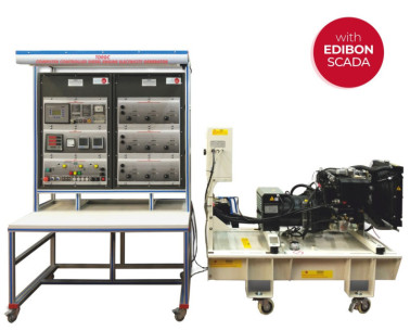
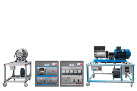
In order to acquire a greater experience with the study of synchronous generators, it is recommended to acquire a set of resistive and inductive loads with the aim of studying the stand-alone operations of synchronous generators (isolated from the national grid). These loads will allow the user to go deeper into the basic concepts about the behaviour of synchronous generators working under load, such as generation and demand in isolated systems, voltage drops or the output voltage control by means of the excitation current regulation.
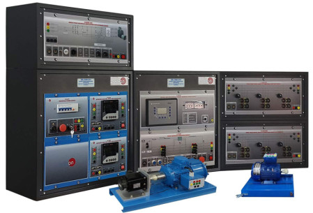
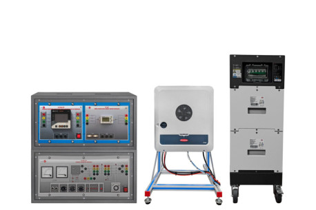
It is also recommended to acquire a kit for the study of faults in synchronous generators, consisting of an advanced differential protection relay with configurable numerical programming which allows showing the features of three-phase differential protection, two power switch modules as interrupting devices, a fault injection module for the injection of single-phase, two-phase or three-phase, to earth, faults and a module with three-phase inductances as buffering element for the faults at the generator induced side.
In addition, it is recommended as well a rotor protection module for the study of faults at the synchronous generator excitation side and a three-phase harmonic filter for the reduction of the harmonics resulting from the regulation of the generator excitation current.
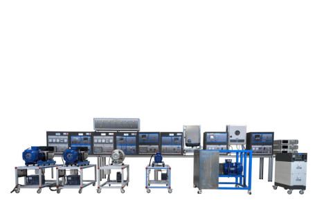
The "AEL-HPSG" is one of the most complete and versatile applications regarding the in-depth study of synchronous generators, both in island and parallel to grid operations. Furthermore, it is compatible with any type of energy transmission line which makes it possible to study the impact of synchronous generators on real grids, analysing events such as power transfer among several machines working in parallel, sudden decouplings and its consequences and endless meanuevers related to electric generators.
Finally, for the most optimal management of the application, it is recommended the Energy Manager and Data Acquisition Software, "EMG-SCADA". This awesome tool allows the user to monitor all the curves for the grid and generator electrical parameters, watch the voltage drops, energy losses in transmission lines and voltage drops. In addition, it allows saving all the acquired data to watch and compare it later. It is possible to see clearly and with accuracy the effects of reactive power compensation on the monitored power curves, maximum and minimum energy demand, load unbalances and the variation of the power factor in the nodes of the system.
 Cookies首选项

 目錄
目錄
 比赛规格
比赛规格