Cookies首选项
Your cart
There are no more items in your cart

 目錄
目錄
 比赛规格
比赛规格
- BS2-PLC
Available
6.2.3.- 用PLC进行仪表控制
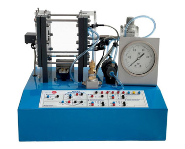
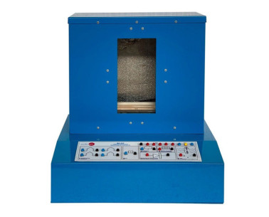
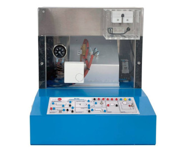
BS2-PLC
用于PLC的温度测试模块
The "BS2-PLC" has been designed to study the use and applications of temperature sensors as a measure device and how to perform a temperature control through a PLC. The unit has a half-open space inside which there is a lamp that heats the...