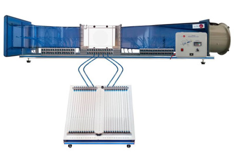
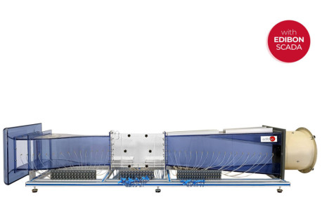
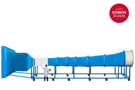
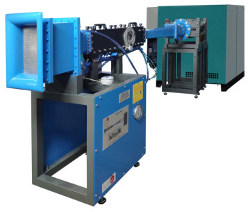
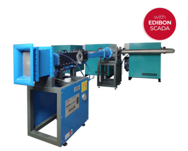
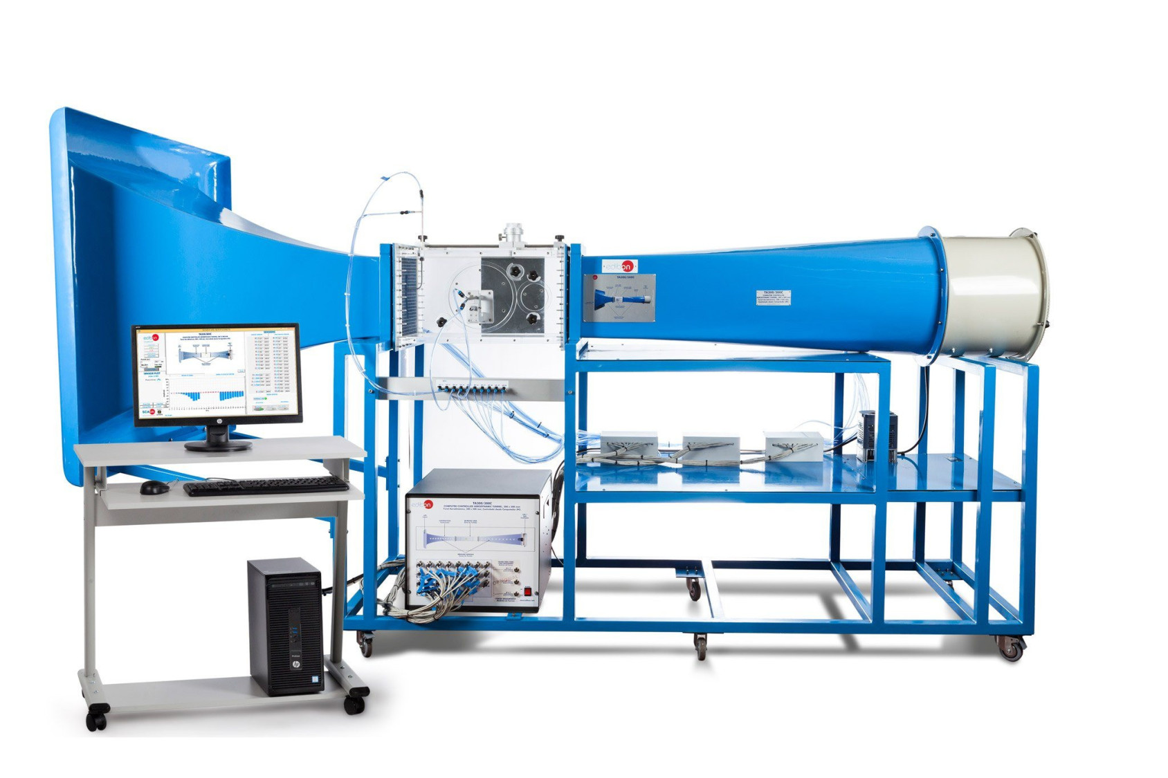
The Computer Controlled Aerodynamic Tunnel, 300 x 300 mm, "TA300/300C", designed by EDIBON, is a wind tunnel designed to study subsonic aerodynamics in a tunnel in open circuit and with incompressible subsonic flow. Air is drawn by a variable speed fan, computer controlled, located at the discharge end of the tunnel. Several models and accessories are available, allowing a comprehensive study of subsonic aerodynamics.
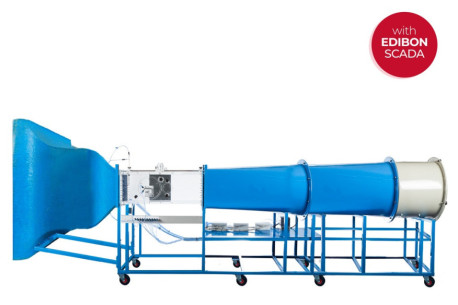
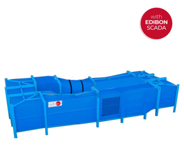
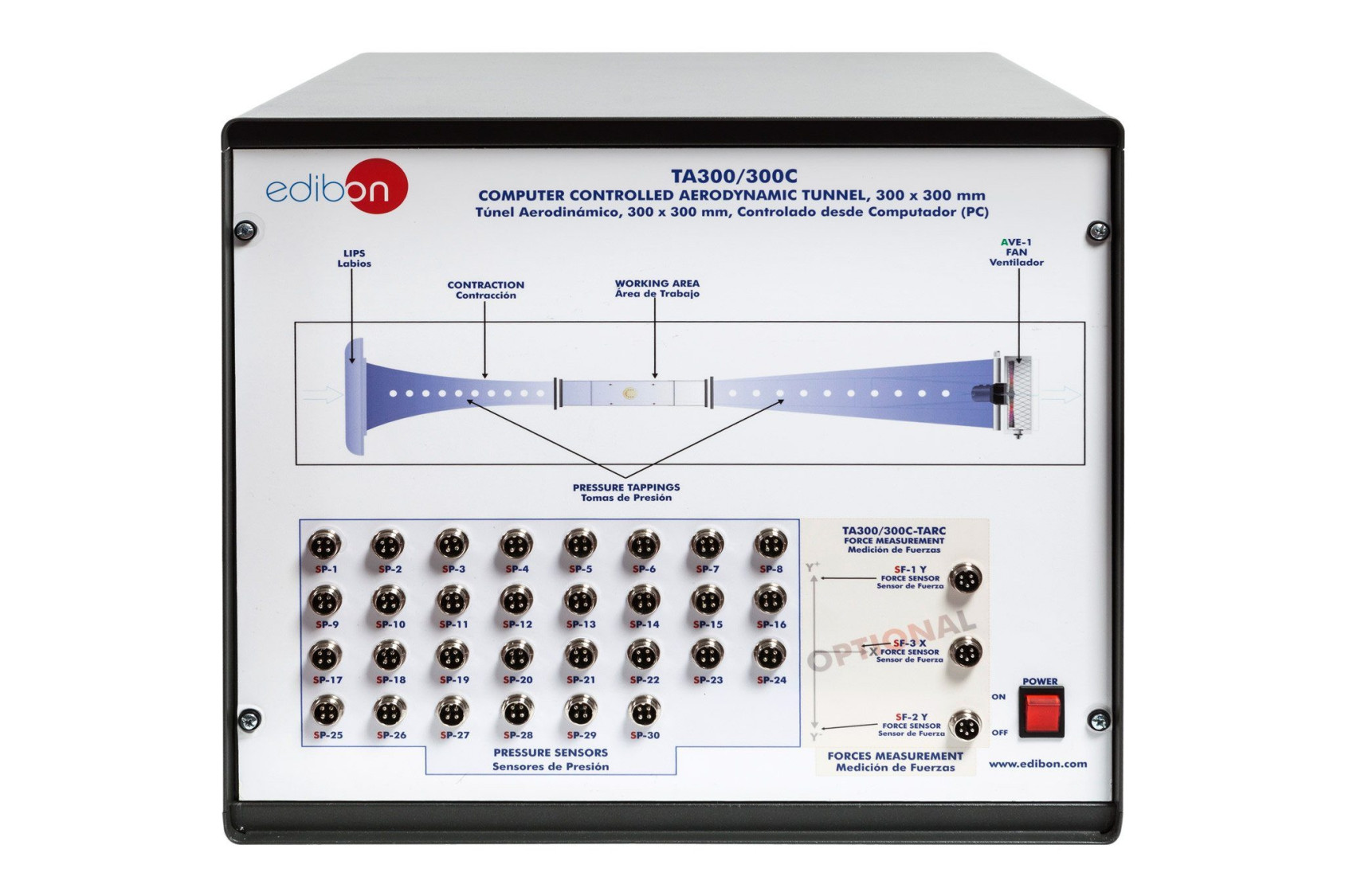
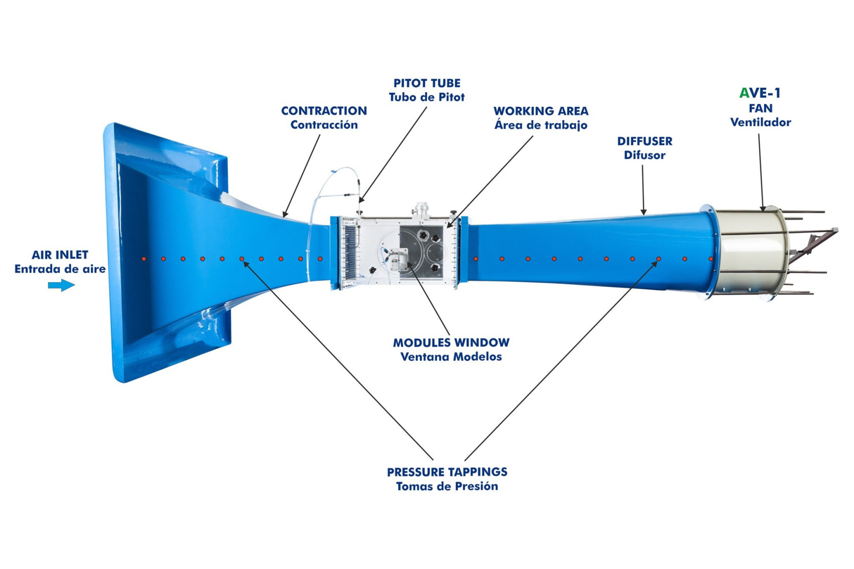
The unit includes several tunnel sections. In the same order in which the flow crosses them, they are: lips, haven section, contraction, working area, diffuser and fan.
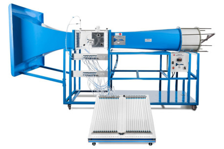
Lips and a haven section are incorporated at the tunnel inlet to reduce the pressure drop and the interferences in the flow. An 9.5:1 contraction ratio and a perfectly studied contour curve of the contraction ensures well developed airflow through the working area.
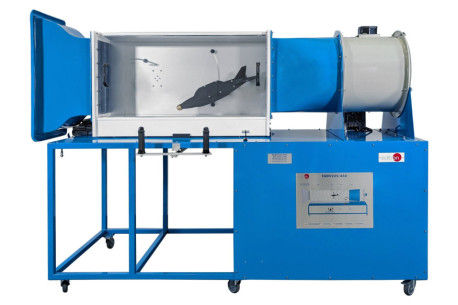
The working area is located after the contraction. It is a constant section tract, where the models to be tested are assembled, and the dimensions of the transverse section is bigger than the models. It is made of clear acrylic resin to allow to observe the models. This section includes a Pitot static tube in the top side to study the static pressure, dynamic pressure and total pressure.
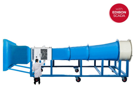
A diffuser is included at the tunnel outlet to avoid the generation of turbulences, which can generate damages in the current quality at the working area.
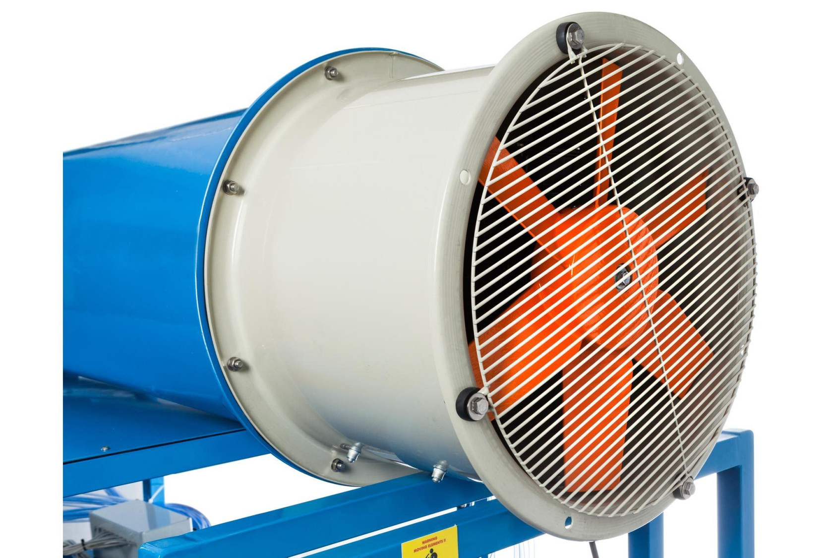
An axial-flow fan, located at the discharge end of the tunnel, provides a more uniform velocity profile at the working area.
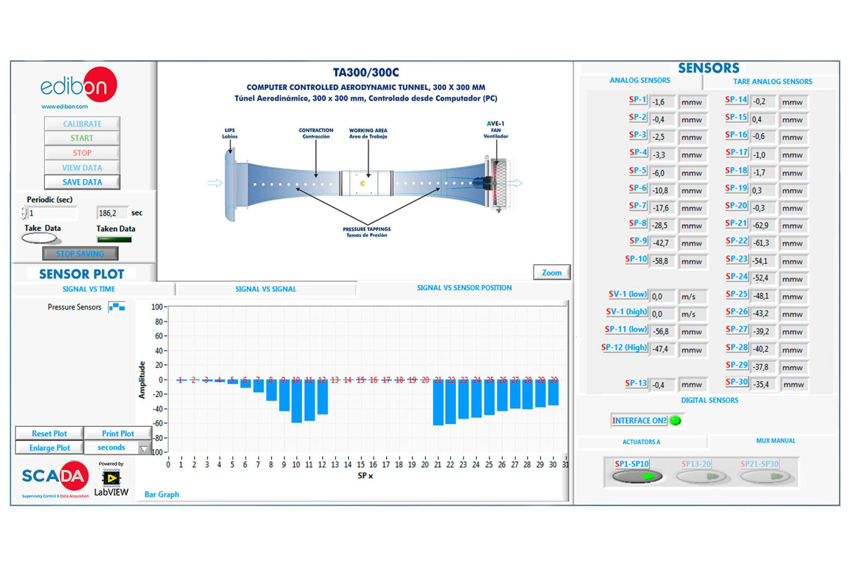
There are sixty different appropriate tappings for the pressure takings (along the tunnel and in the different models). The unit includes thirty differential pressure sensors to measure the static pressure.
The models are mounted on a circular hatch, and they are coupled to the working area to seal the opening. They are secured by knobs on the side wall of the working area.
This Computer Controlled Unit is supplied with the EDIBON Computer Control System (SCADA), and includes: The unit itself + aControl Interface Box + a Data Acquisition Board + Computer Control, Data Acquisition and Data Management Software Packages, forcontrolling the process and all parameters involved in the process.
 Cookies首选项


 目錄
目錄
 比赛规格
比赛规格


