Technical Training in the Field of Continuum Mechanics
Due to the growing research about industrial application materials, we are seeing increasingly complex techniques and test procedures in industries such as automotive, infrastructures, and manufacturing. For that reason, technicians and engineers need an up-to-date and adapted technical training that can help them understand the fundamentals on which those techniques are based.
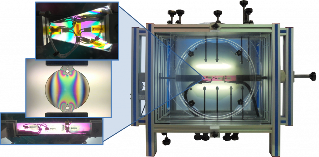
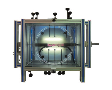
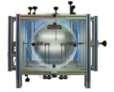
In response to that demand, EDIBON has designed the EFO unit, applied to the strength of materials branch, and focused on the study of continuum mechanics through photoelasticity. This technique focuses on the analysis of stresses and strains, as well as their distribution and direction in systems subjected to external stresses. To that end, this unit includes a series of flat models made of materials with characteristic optical properties. When applying external loads, those properties make a series of isochromatic fringes visible on the models, whose formation pattern closely relates to the stress state experienced. Consequently, we can observe the stress distribution on the model at a glance and prove well known theoretical principles (Saint-Venant’s Principle, Navier’s Law, and more).
Figure 1. EFO Unit With Flat Testing Model in Which Isochromatic Lines Can Be Observed as a Result of the Stress State in the Model.
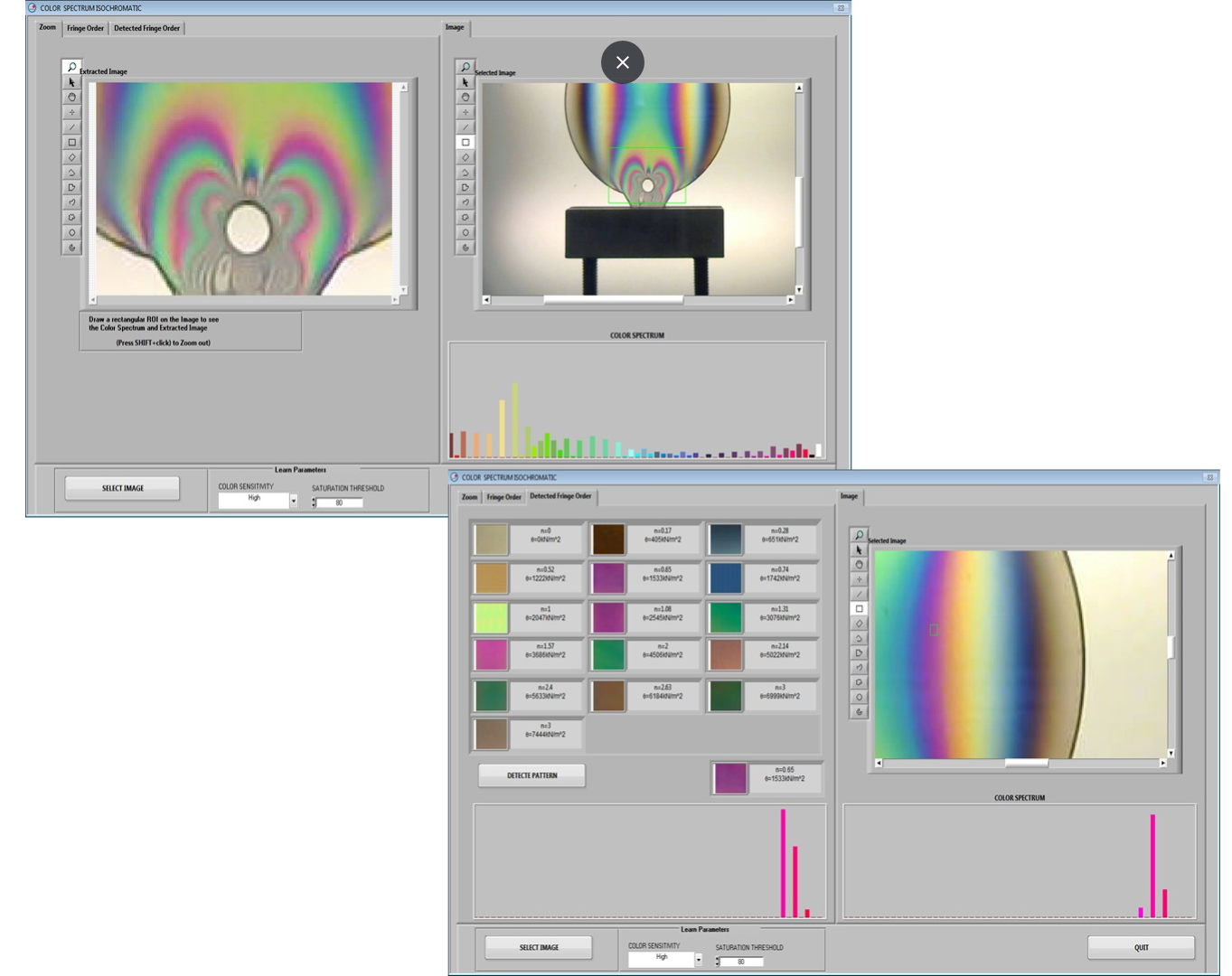
Likewise, the EFOC (Photoelasticity Unit with Strain Gauges Measurements System) and EFOV (Photoelasticity Unit with Artificial Vision System) units appear as variants of the EFO (Photoelasticity Unit). The first one includes testing models equipped with strain gages that allow for determining the mechanical properties of the materials (Young’s modulus, Poisson’s ratio, and more). The second unit also includes a high-resolution camera for image acquisition and sensors to measure applied forces and strains. Thus, we can study the stress state of the tested models based both on the data acquired by the sensors and from the spectral analysis of the isochromatic and isocline lines observed in the images captured by the camera.
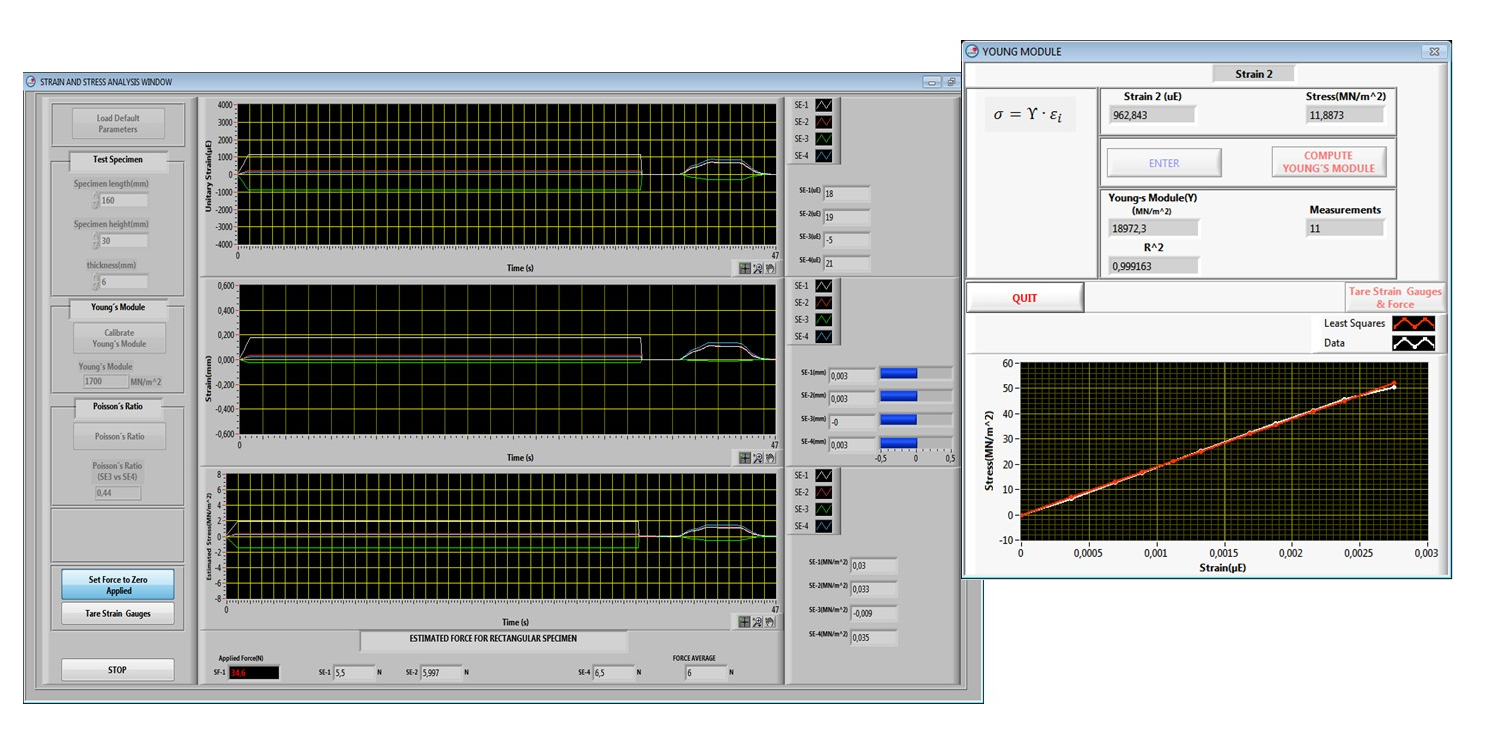
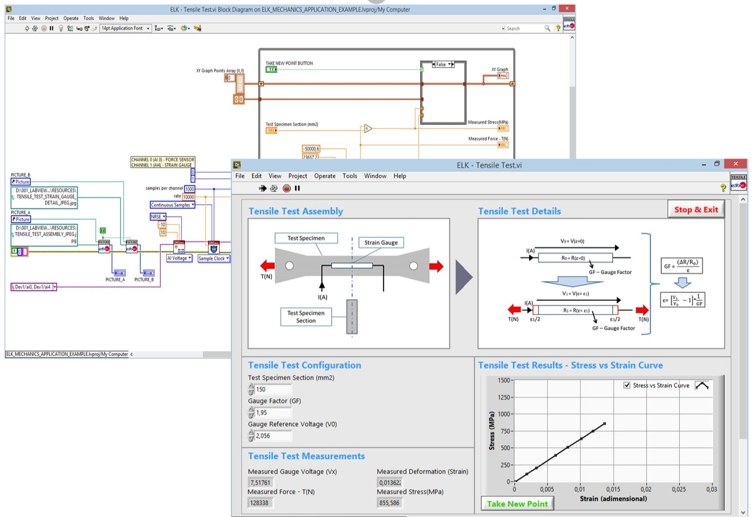
Figure 2. SCADA Software Obtains the Mechanical Properties From the Data Acquired (Young’s Modulus)
We can supply these units with a SCADA software developed with LabVIEW, as well as with high-performance and low-latency multifunction DAQ devices, such as the PCIe-6321. Thanks to these technologies, we can continuously measure the values of forces, stresses, and strains. We use the NI Vision Acquisition Software for image processing, accurately obtaining multiple results associated to the study of the isochromatic fringes shown in the models.
Figure 3. SCADA Software for the Spectral Analysis of the Isochromatic Fringes Observed in the Tested Models
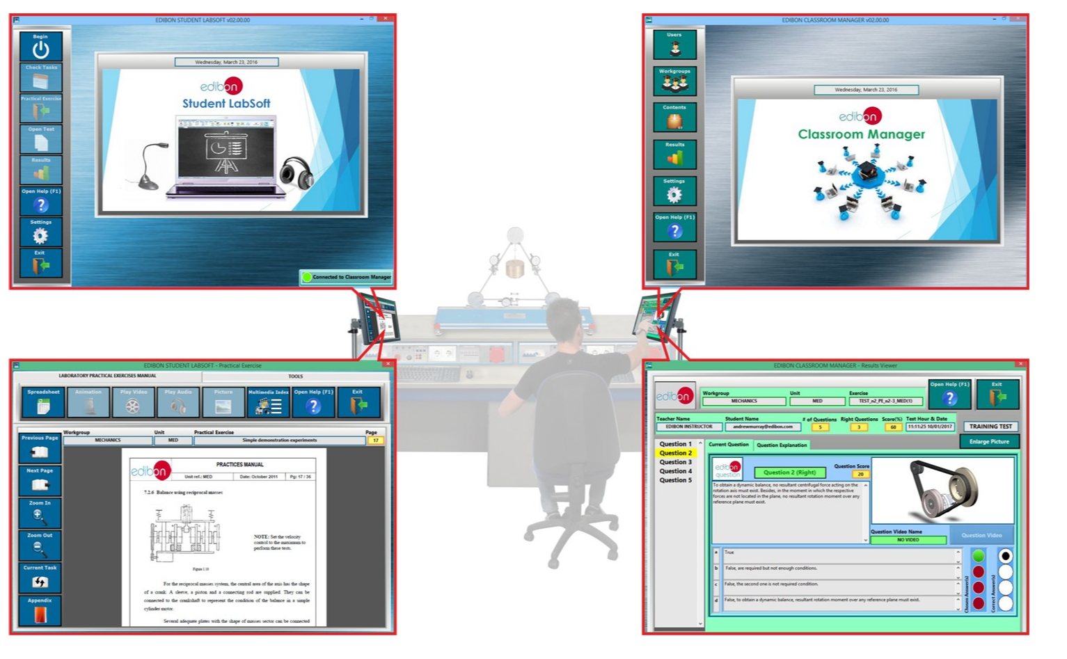
All the units include two additional software packages, an interactive computer-aided instruction (ICAI) software and ELK (Toolkit de Mecánica del Kit).
We can use the ICAI software to perform practical exercises and tests with the units, assess users, obtain statistical results about their progress, and more.
We can use the ELK software development kit to get started with LabVIEW in a practical way having access to the source code of applications for these units and widening their functions. This results in customizable SCADA systems and helps users gain a better understanding and use of the units.
Figure 4(a). Interactive Computer-Aided Instruction (ICAI) Software of the Mechanics Area
Figure 4(b). Mechanics Toolkit of the Software Development Kit Based on LabVIEW (ELK).
 Cookies首选项