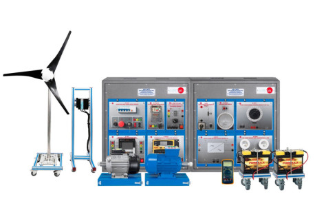
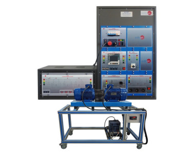
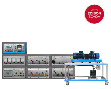
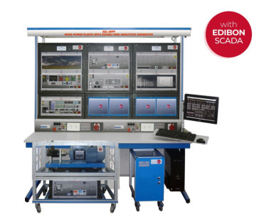
MINI-EEEC Grundgerät für Windenergie, computergesteuert (PC)

COMPUTER CONTROLLED WIND ENERGY BASIC UNIT - MINI-EEEC

Unit: MINI-EEEC. Computer Controlled Wind Energy Basic Unit

COMPUTER CONTROLLED WIND ENERGY BASIC UNIT - MINI-EEEC

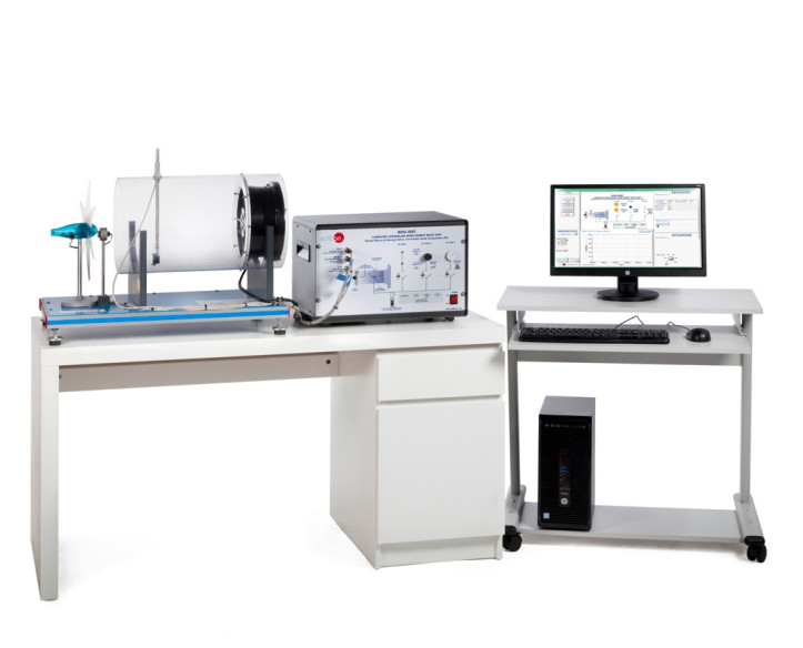
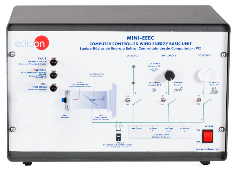
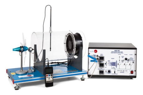
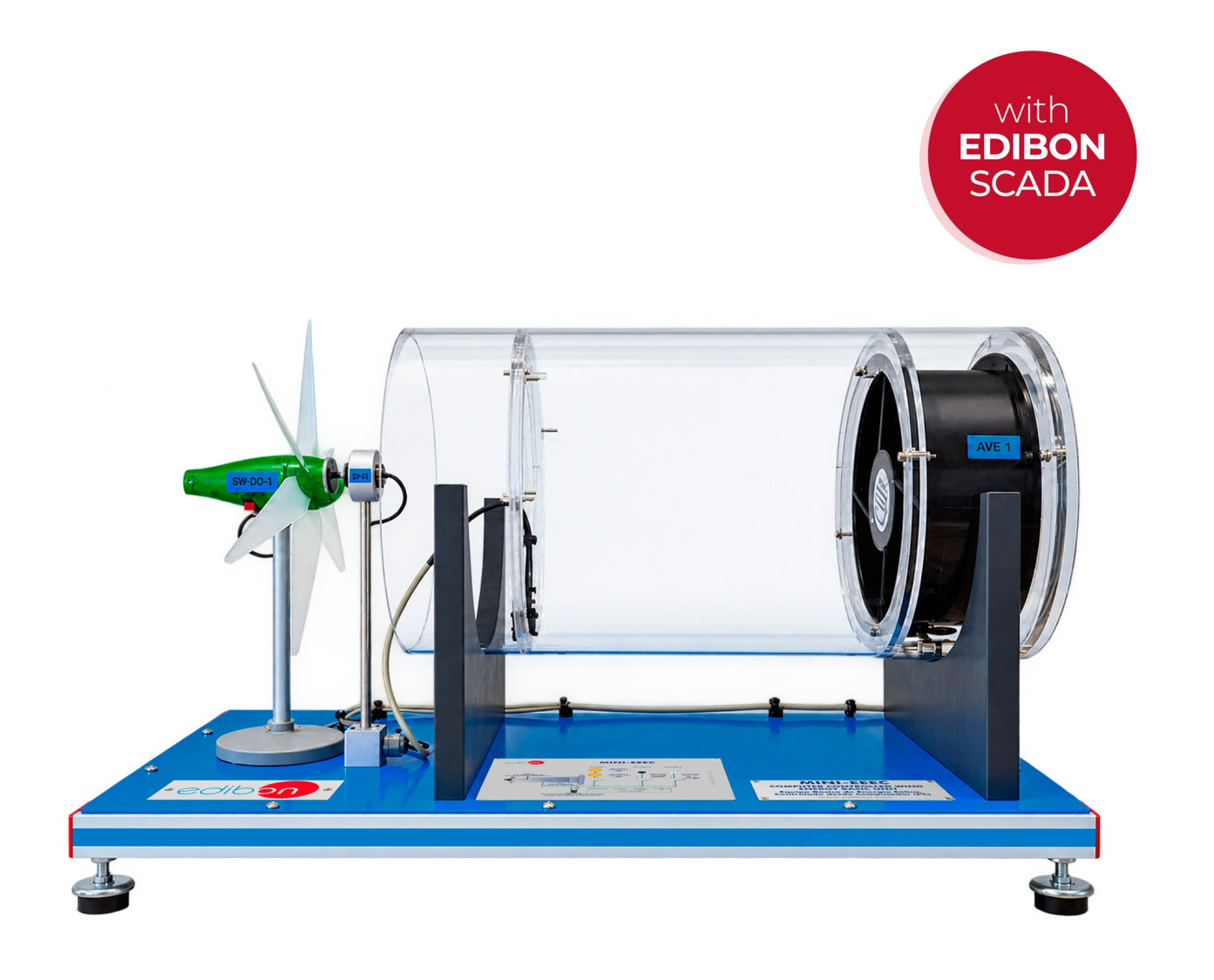
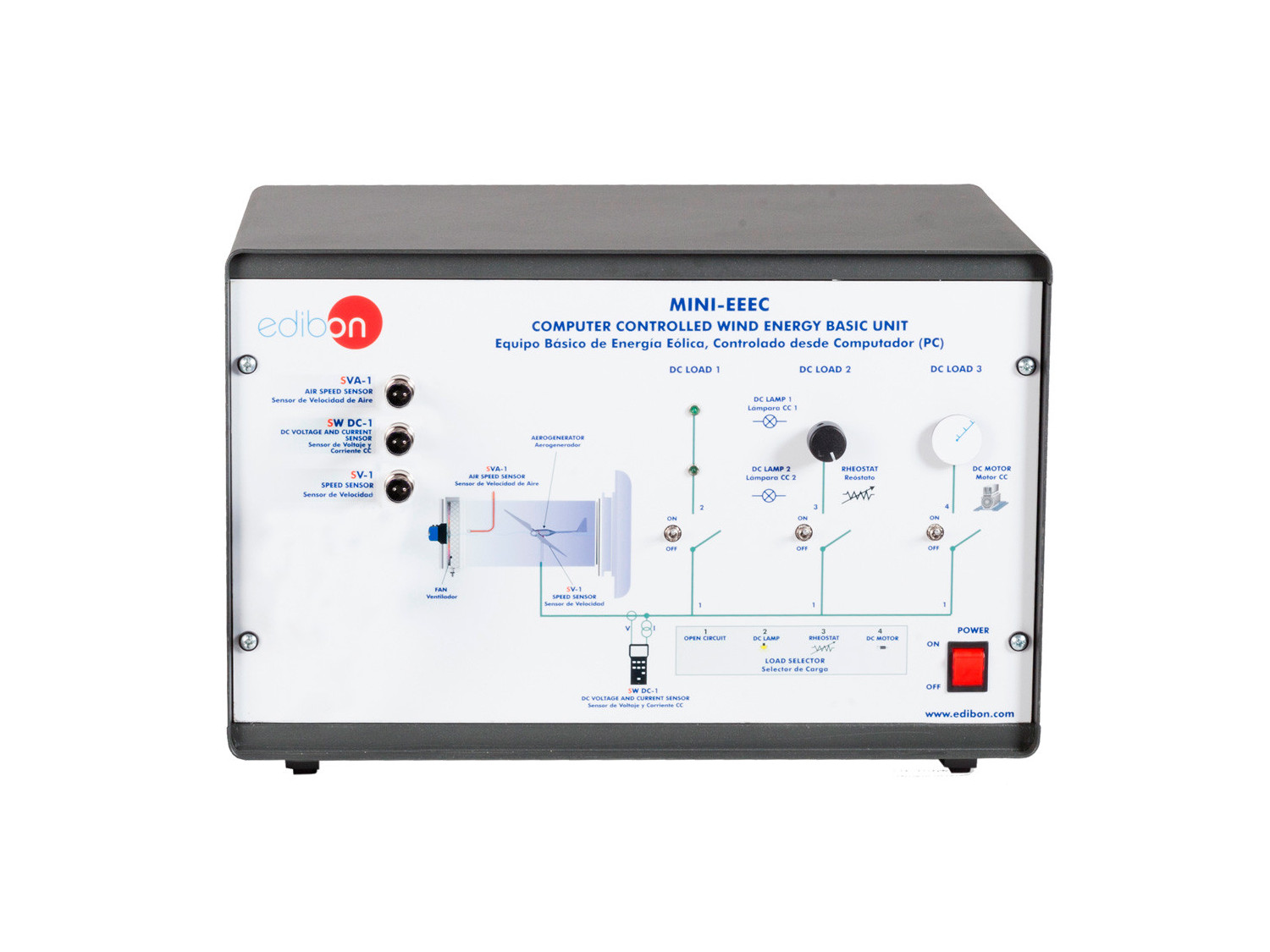
Complete MINI-EEEC unit

COMPUTER CONTROLLED WIND ENERGY BASIC UNIT - MINI-EEEC

Unit details

COMPUTER CONTROLLED WIND ENERGY BASIC UNIT - MINI-EEEC

MINI-EEEC/CIB. Control Interface Box: The Control Interface Box is part of the SCADA system

COMPUTER CONTROLLED WIND ENERGY BASIC UNIT - MINI-EEEC

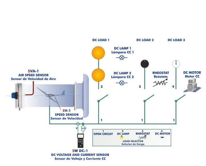
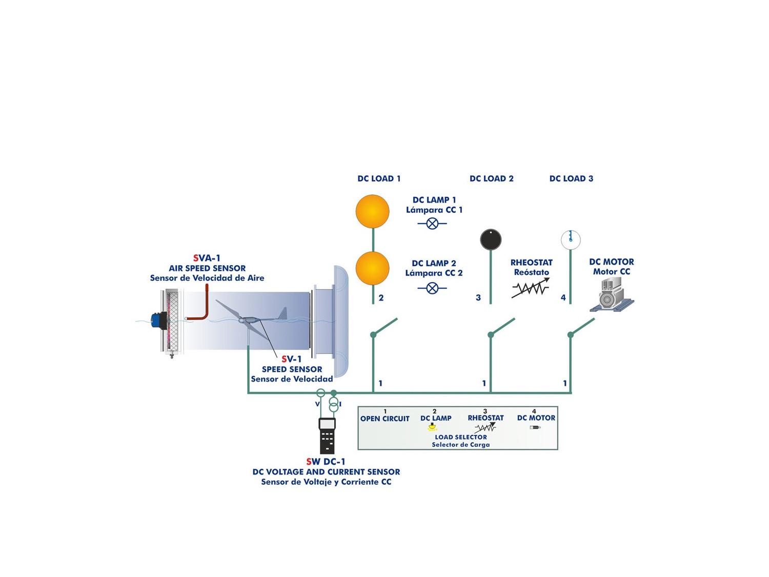
Process diagram and unit elements allocation

COMPUTER CONTROLLED WIND ENERGY BASIC UNIT - MINI-EEEC

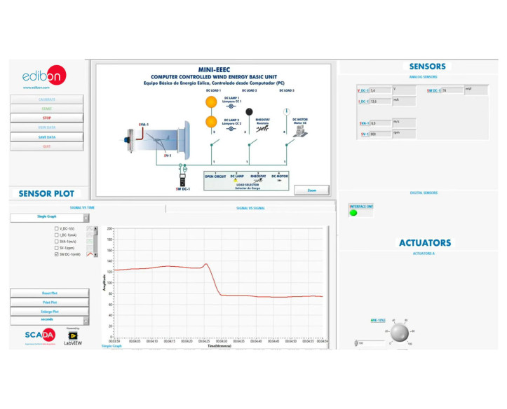
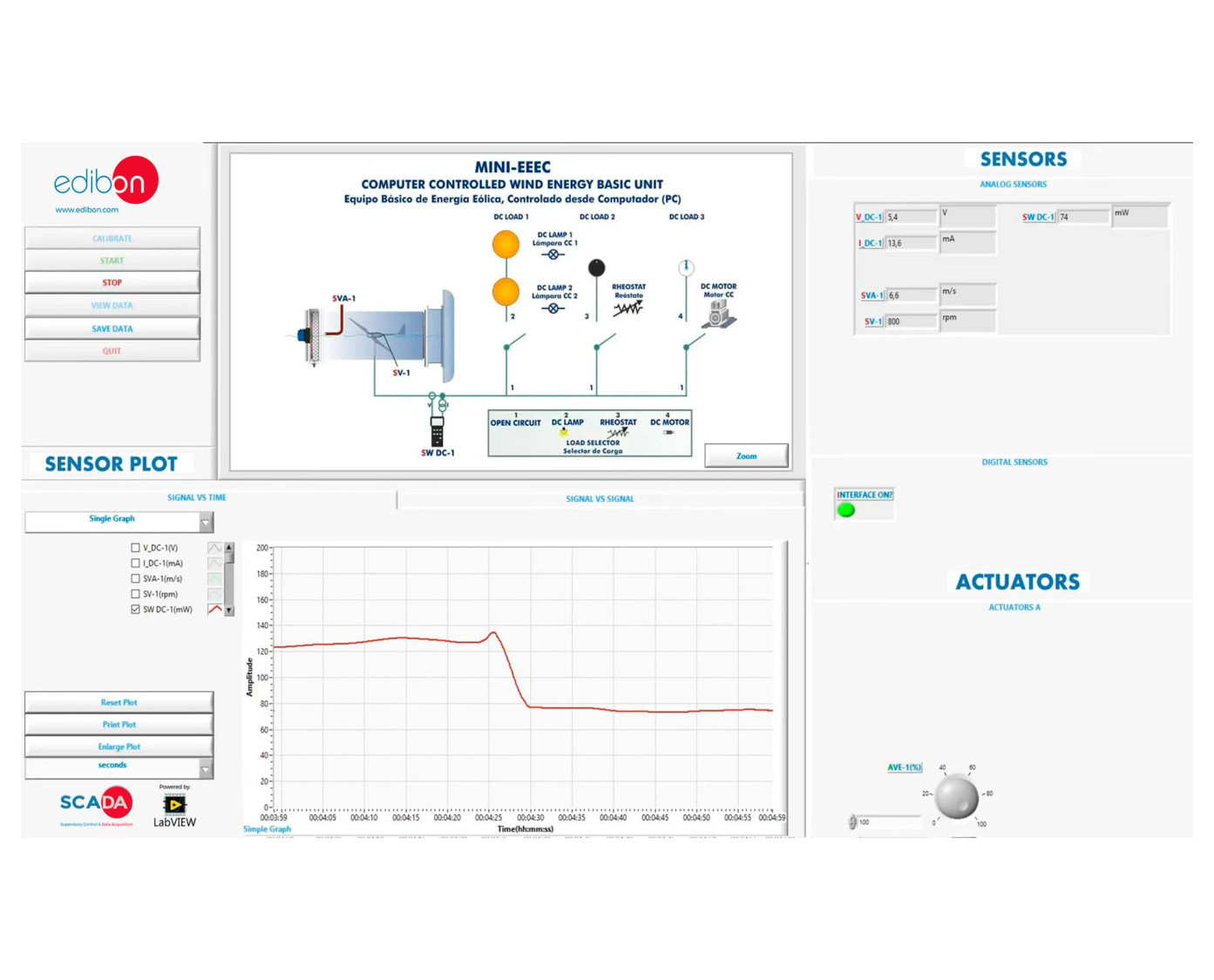
MINI-EEEC/SOF. MINI-EEEC Software. Main Screen

COMPUTER CONTROLLED WIND ENERGY BASIC UNIT - MINI-EEEC

INNOVATIVE SYSTEME

The Computer Controlled Wind Energy Basic Unit, with SCADA, "MINI-EEEC", has been designed by EDIBON to experimentally study the conversion of wind energy into electrical energy and analyze the influence of wind speed, blade number, and connected load on rotational speed, voltage, current, generated power, and wind turbine efficiency.

Allgemeine Beschreibung anzeigen

ÄHNLICHE NEUIGKEITEN

ALLGEMEINE BESCHREIBUNG

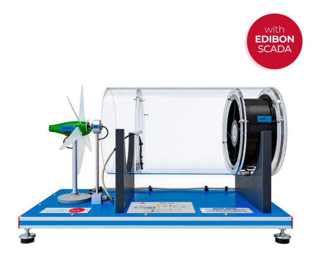
The Computer Controlled Wind Energy Basic Unit, with SCADA, "MINI-EEEC", has been designed by EDIBON to experimentally reproduce the operation of a wind turbine under different wind and electrical load conditions. By varying air speed, blade configuration, and load conditions, the unit allows users to obtain wind turbine characteristic curves, study the relationships between operating variables, and experimentally determine generated power and energy conversion efficiency.

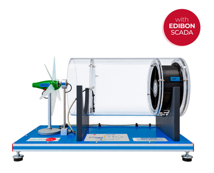
The unit includes a transparent air tunnel in which a computer-controlled variable-speed axial fan generates the airflow required to drive the wind turbine. Adjusting the fan rotational speed allows wind conditions to be varied in a controlled manner, while an air speed sensor measures this variable so it can be related to wind turbine performance.

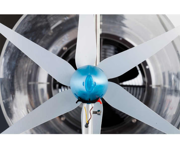
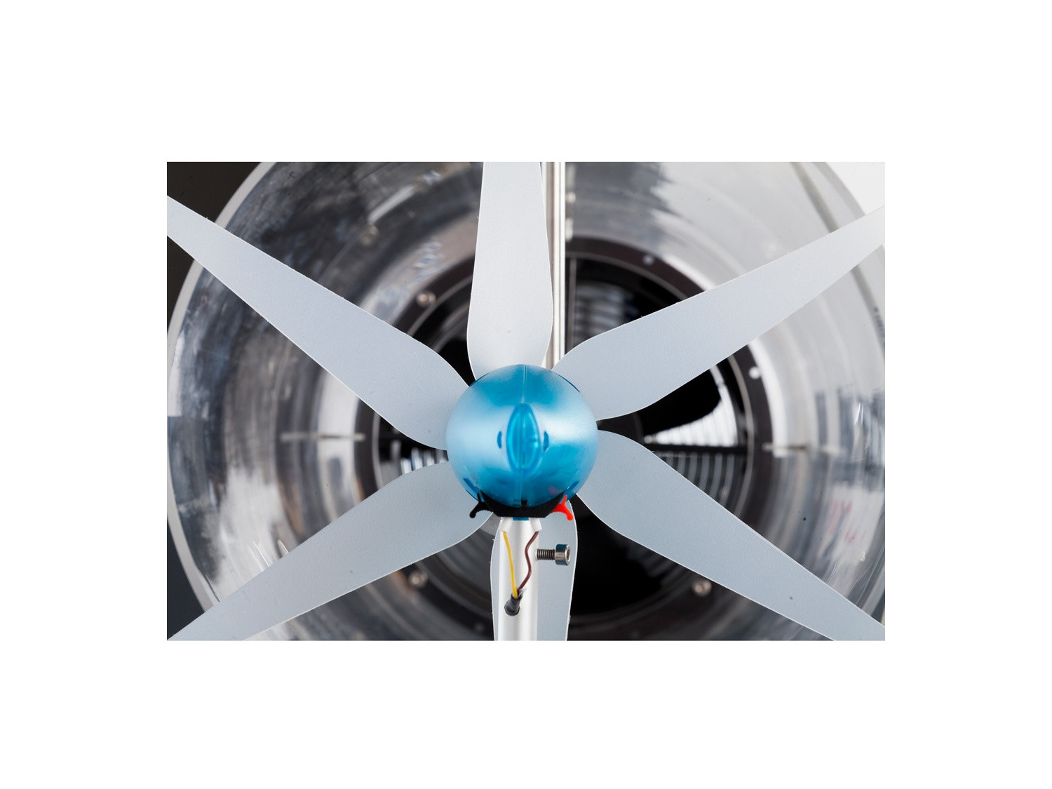
The wind turbine includes a rotor that can be configured with two, three, or six blades, allowing its operation to be compared under different configurations. The airflow drives the rotor, and the generator converts its kinetic energy into electrical energy. A rotational speed sensor measures wind turbine speed, making it possible to study its behavior as a function of wind speed, blade number, and applied load.

The generated electrical energy is analyzed using a DC load module that includes two LEDs, a rheostat, and a DC motor. A load selector provides four operating conditions: open circuit, direct connection to the LEDs, connection to the rheostat, or connection to the DC motor. These configurations allow users to study the effect of different loads on wind turbine operation and analyze its electrical response.

A voltage and current sensor measures the electrical quantities supplied by the generator, from which the generated electrical power is determined. The instrumentation allows users to relate air speed, rotational speed, voltage, current, and power, as well as study wind turbine characteristic curves at constant wind speed and constant rotational speed. It also enables comparisons of generated power according to blade number and experimental determination of efficiency.

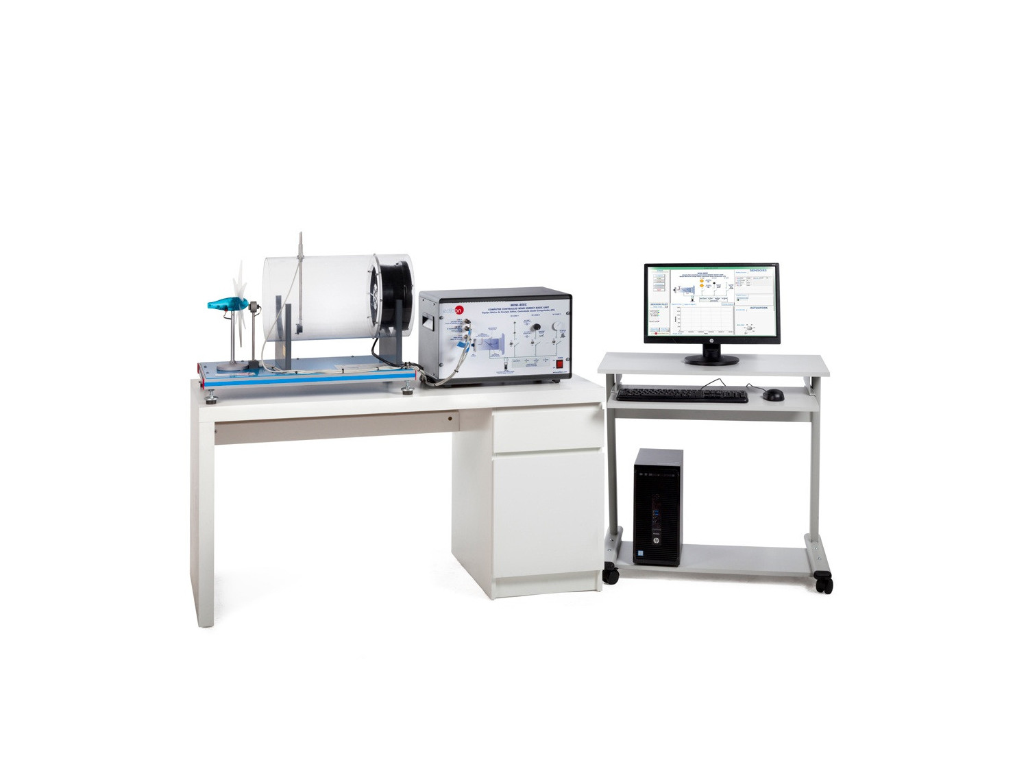
Computer control allows users to adjust fan speed, simultaneously display measured variables, and record results during experiments. It also enables real-time graphical representation of measured quantities and relationships between variables, such as power versus air speed or power versus wind turbine rotational speed. Acquired data can be stored and compared across different experimental conditions. The unit also supports sensor calibration exercises and real-time modification of control parameters.

This Computer Controlled Unit is supplied with the EDIBON Computer Control System (SCADA), and includes: The unit itself + a Control Interface Box + a Data Acquisition Board + Computer Control, Data Acquisition and Data Management Software Packages, for controlling the process and all parameters involved in the process.

ÜBUNGEN UND GEFÜHRTE PRAKTIKEN

GEFÜHRTE PRAKTISCHE ÜBUNGEN IM HANDBUCH ENTHALTEN

  1. Study of the aerogenerator operation depending on the wind speed variation.
  2. Determination of the aerogenerator characteristic parameters.
  3. Study of the differences in the operation by using the three available blades'configurations (aerogenerator with six, three or two blades).
  4. Study of the influence of the load variation in the aerogenerator.
  5. Study of voltage, power and current.
  6. Experimental determination of efficiency.
  7. Study of the power generated by the aerogenerator depending on the wind speed.
  8. Study of the power generated by the aerogenerator depending on the number of blades.
  9. Determination of the wind energy measurement.
  10. Study of the characteristic curve of the aerogenerator at constant wind speed.
  11. Study of the characteristic curve of the aerogenerator at constant revolutions.
  12. Study of the DC loads connection.
  13. Sensors calibration.

MEHR PRAKTISCHE ÜBUNGEN FÜR DAS GERÄT

Other possibilities to be done with this unit:

  1. Many students view results simultaneously. To view all results in real time in the classroom by means of a projector or an electronic whiteboard.
  2. Open Control, Multicontrol and Real Time Control. This unit allows intrinsically and/or extrinsically to change the span, gains, proportional, integral, derivative parameters, etc, in real time.
  3. The Computer Control System with SCADA allows a real industrial simulation.
  4. This unit is totally safe as uses mechanical, electrical/electronic, and software safety devices.
  5. This unit can be used for doing applied research.
  6. This unit can be used for giving training courses to Industries even to other Technical Education Institutions.
  7. Control of the MINI-EEEC unit process through the control interface box without the computer.
  8. Visualization of all the sensors values used in the MINI-EEEC unit process.
  9. By using PLC-PI additional 19 more exercises can be done.
  10. Several other exercises can be done and designed by the user.

ÄHNLICHE VERFÜGBARE GERÄTE

QUALITÄT

KUNDENDIENST

Informationen anfordern