FME07 Gerät der Druckverluste in Rohrleitungen
INNOVATIVE SYSTEME
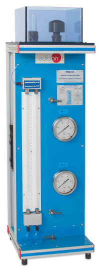
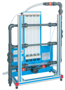
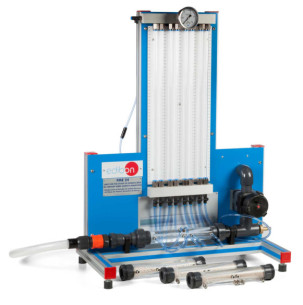
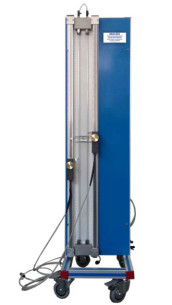
With the Energy Losses in Pipes, "FME07", designed by EDIBON, the user will be able to measure the head losses generated in a pipeline for different flow rates in both laminar and turbulent regimes.
Erweiterungen
Laboratorien
ÄHNLICHE NEUIGKEITEN
ALLGEMEINE BESCHREIBUNG
With the Energy Losses in Pipes, "FME07", designed by EDIBON, the user will be able to measure the head losses generated in a pipeline for different flow rates in both laminar and turbulent regimes.
The unit consists of the following elements, used in combination with the Hydraulics Bench (FME00) or the Basic Hydraulic Feed System (FME00/B):
- Pipe with quick connector to be coupled to the water outlet’s mouthpiece at the Hydraulics Bench (FME00) or the Basic Hydraulic Feed System (FME00/B).
- 6 mm external/4 mm inner diameter metallic test pipe.
- One water column differential manometer.
- Constant height tank.
- Two Bourdon type manometers.
ÜBUNGEN UND GEFÜHRTE PRAKTIKEN
GEFÜHRTE PRAKTISCHE ÜBUNGEN IM HANDBUCH ENTHALTEN
- Energy loss in pipes for a turbulent regime.
- Determination of the energy loss in a turbulent regime.
- Determination of the number of Reynolds for a turbulent regime.
- Energy loss in pipes for a laminar regimen.
- Determination of the energy loss factor f for a pipe in laminar regime.
- Determination of Reynolds number for the laminar regime.
- Determination of the kinematic viscosity of water.
ERGÄNZENDE AUSRÜSTUNG
Gerät der lokalen Druckverluste
Gerät des hydraulischen Widders
Gerät für Rohrgitter, Basis
Gerät für das Studium von porösen Betten in Venturi-Rohren (Darcy-Gleichung)
System zur Datenerfassung und Sensorik
QUALITÄT

KUNDENDIENST

 Cookie-Präferenzen

