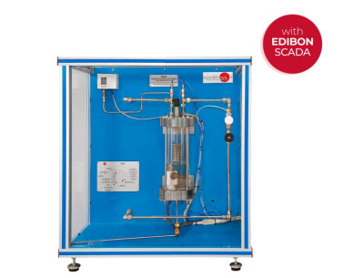
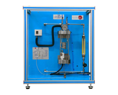
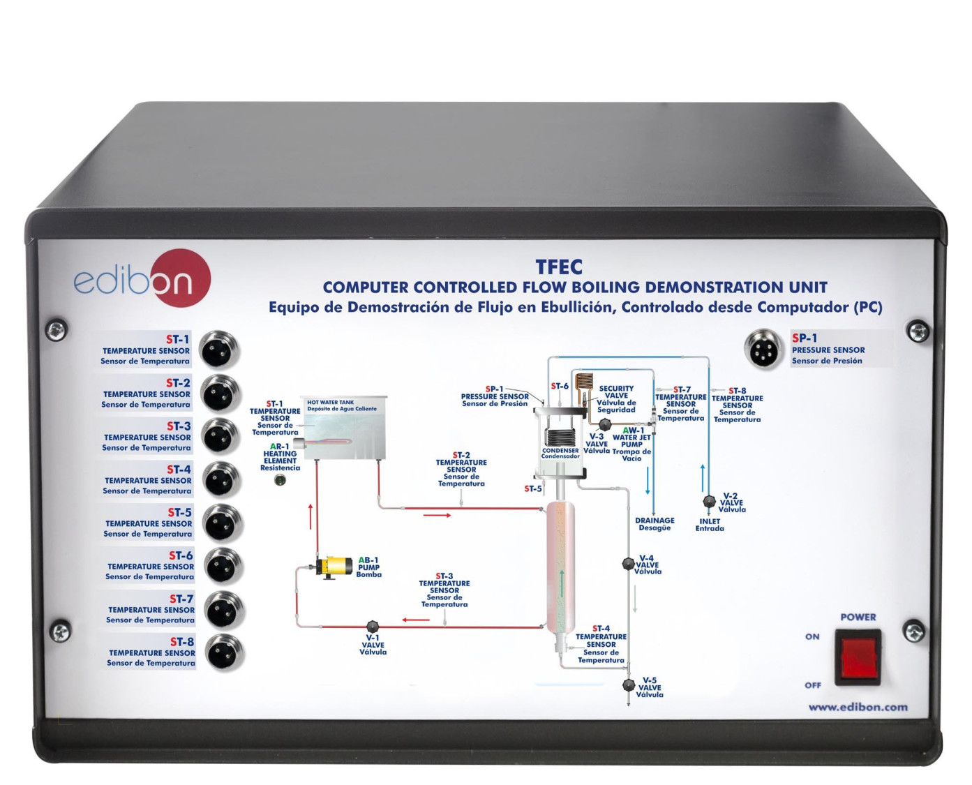
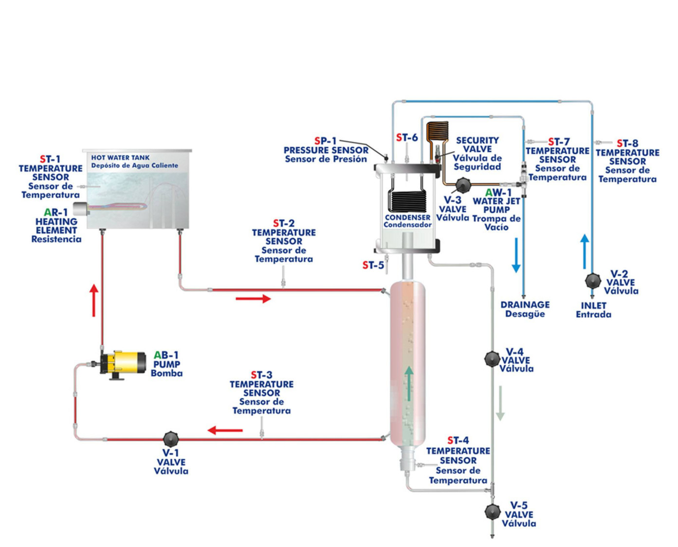
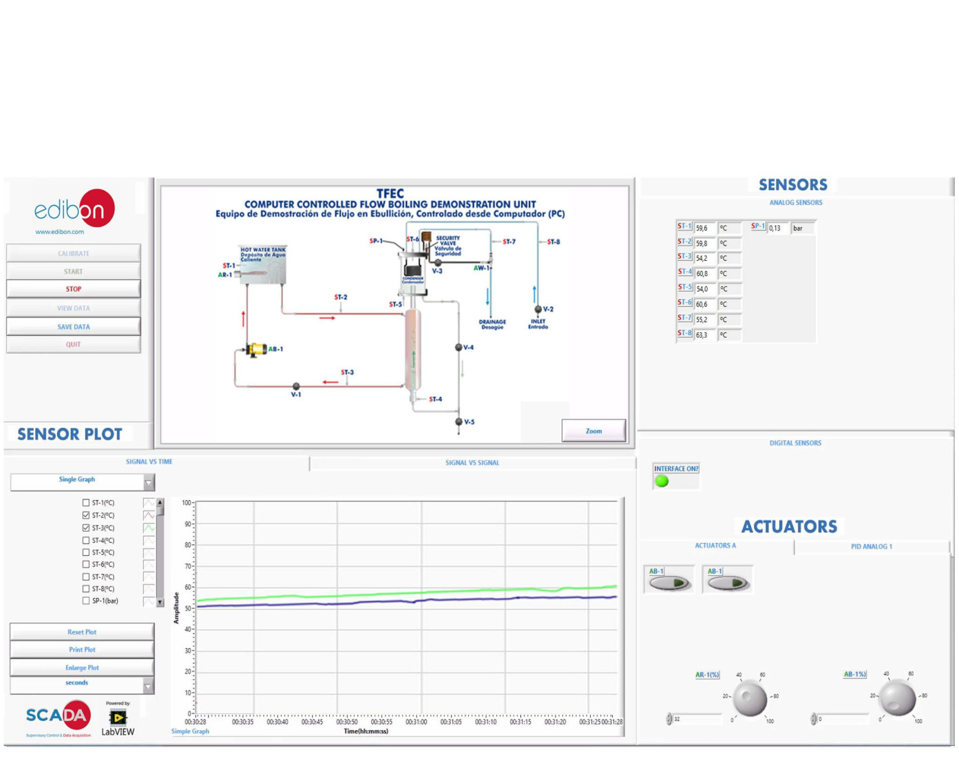
The Computer Controlled Flow Boiling Demonstration Unit, "TFEC", has as main component an experimental tube made of two glass concentric tubes. In these tubes two fluids flow crosscurrent: refrigerant, which flows by convection and in an ascendant way through the internal tube, and hot water, which flows in a descendant way through the external tube. This unit has been designed for using SES36 refrigerant gas, free of CFC´s, compatible with the Environment.
Refrigerant circuit:
The main circuit will be where the different stages of the two-phase flow will be visualised by student.
This circuit is composed of:
- Internal glass concentric tube, where the refrigerant liquid flows.
- Regulation valve for the input flow to the experimental tube.
- Condensing chamber, that is complemented with an absolute pressure sensor which allows to determine the presence of air in the system, a security valve to protect it from possible over pressure. With a temperature sensor the refrigerant temperature into the tank will be visualized. Other temperature sensor shows the temperature of the saturated vapour in the condensing chamber.
Heating circuit:
Basically, this second circuit is composed of:
- External glass concentric tube, through which hot water flows to transfer the hot to the internal tube fluid.
- Thermostatic bath, with a resistance of 600 W. It heats the water in the tank.
- Centrifugal pump for recirculation.
The electric power consumed by the resistance is controlled, from the computer, by PID over the bath temperature.
The heat transfer can be valued because there are two temperature sensors in the refrigerant liquid, in the input and in the output of the concentric tubes.
Finally the condensing chamber has a security valve. It also can be used if we want to carry out the refrigerant charge operation.
This Computer Controlled Unit is supplied with the EDIBON Computer Control System (SCADA), and includes: The unit itself + a Control Interface Box + a Data Acquisition Board + Computer Control, Data Acquisition and Data Management Software Packages, for controlling the process and all parameters involved in the process.
 Настройки cookie


 Каталог
 Спецификации конкурса


