TRRC Computer Controlled Refrigeration Unit with Refrigeration and Freezing Chamber
혁신적인 시스템
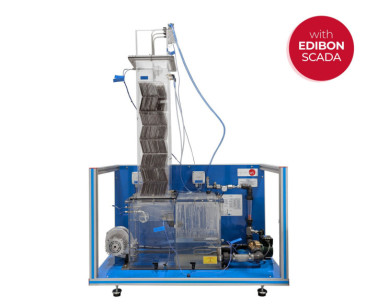
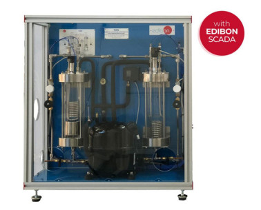
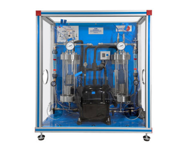
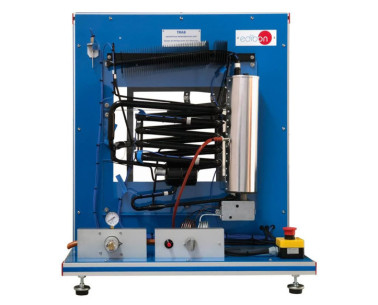
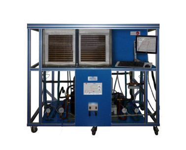
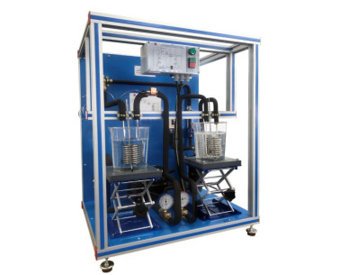
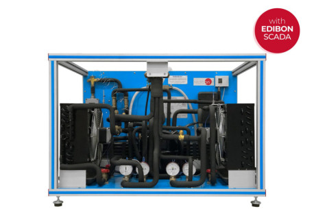
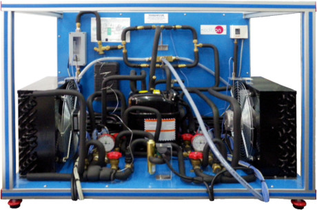
The Computer Controlled Refrigeration Unit with Refrigeration and Freezing Chamber, "TRRC", has been designed by EDIBON to study a refrigeration system with two different chambers at different temperature.
확장
실험실
관련 뉴스
일반적인 설명
The procedure performed by the Computer Controlled Refrigeration Unit with Refrigeration and Freezing Chamber, "TRRC", consists of the following stages:
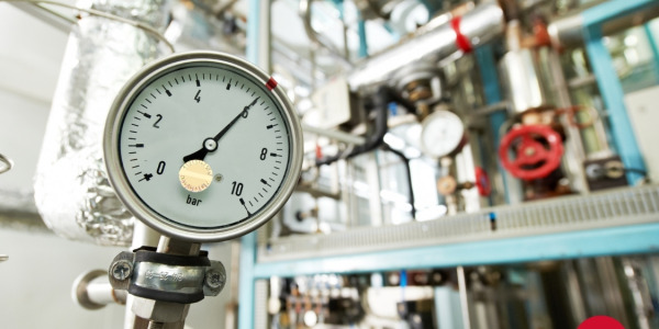
- Compression: This stage begins when the refrigerant enters the compressor. This refrigerant is compressed, increasing its pressure and temperature. The unit includes a pressure sensor, a manometer and a temperature sensor to measure those variables.
- Condensation: The refrigerant is driven to the condenser, where its temperature decreases, at constant pressure, and its state changes to liquid state. This change is explained because heat is given to the external air in the condenser. At the end of this stage, the pressure and temperature of the refrigerant are measured with a manometer and a temperature sensor. After leaving the condenser, the refrigerant goes to the accumulator, where it is stored to a greater or lesser extent in function of the chambers demand, and to a filter, to retain condensate particles. The flow is measured by a flow sensor. Before the expansion, it’s possible to cool the refrigerant in a heat exchanger to get down the temperature (supercooling process), to increase the efficiency of the process.
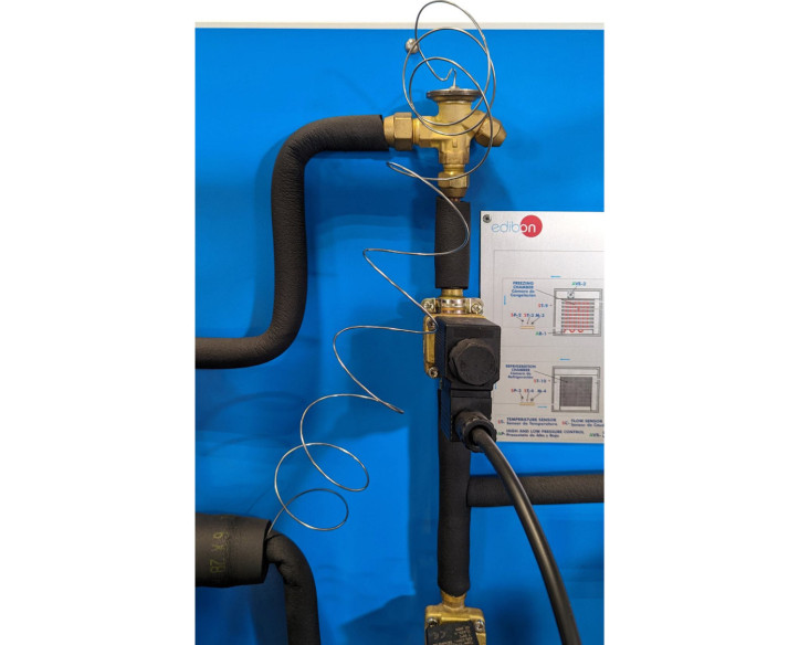
- Expansion: From that point, with two solenoid valves, the circuit branches in two paths covered simultaneously, one per chamber. After the valve that defines the path, the pressure and temperature of the refrigerant decreases in the expansion valve and its states becomes a mixture of liquid and vapor. At the end of this stage the pressure and temperature of the refrigerant is measured by a pressure sensor, a manometer and a temperature sensor. Solenoid valves enable the individual or parallel operation of the evaporators in the two chambers.
- Evaporation: Finally, the refrigerant enters the evaporator, where it is gradually transformed in gas due to the heat absorbed coming from the inside of the chamber. This process is carried out in the refrigeration chamber at a pressure and temperature higher than in the freezing chamber thanks to a valve that regulates the evaporation pressure, which enables to evaporate at higher pressures and temperatures. In the freezing chamber there is an electric heating element to remove any possible layer of frost after finishing the process. The pressure and temperature of the refrigerant are measured at the outlet of each chamber with a manometer and a temperature sensor and the effect of the evaporation pressure controller on the overall process is examined.
- The flows coming from both chambers are mixed at the end of this stage and then they pass through a liquid separator to retain liquid particles before entering the compressor again. The inlet conditions to the compressor are measured by a pressure sensor, a manometer and a temperature sensor. There is a pressure switch located between the inlet and outlet of the compressor that stops the process when hazardous pressures are reached.
All the components are arranged clearly in the unit and a signal lamp in the process schematic indicate the operating state of the selected components.
This Computer Controlled Unit is supplied with the EDIBON Computer Control System (SCADA), and includes: The unit itself + a Control Interface Box + a Data Acquisition Board + Computer Control, Data Acquisition and Data Management Software Packages, for controlling the process and all parameters involved in the process.
연습 및 가이드
매뉴얼에 포함 된 가이드 실기 연습
- Representation of the thermodynamic cycle in the p-h log diagram.
- Determination of the refrigeration capacity.
- Determination of the compressor work.
- Determination of the coefficient of performance (COP).
- Design and components of a refrigeration system with two evaporators.
- Sensors calibration.
장비로 수행 할 수있는 더 많은 실용적 연습
- Properties of the refrigerant R-513a.
- Enthalpy-pressure diagram for the refrigerant R-513a.
- Study of the refrigerant subcooling effect.
- Study of the compressor and its function.
- Study of the evaporators and their functions.
- Study of the condenser and its function.
- Study of the expansion valve and its function.
- Study of the evaporation pressure control valve.
- Study of the defrost heater and its function.
- Study of the pressure switches and their function.
- Study of the effect of air in a refrigeration system.
- Temperature control.
- Measurement of power.
- Determination of the electrical performance of the compressor.
- Study of the solenoid valve and its function.
- Analysis of the pressure ratio in the behavior of the system.
- Relation between pressure and temperature.
- Study of the structure and elements of a refrigeration system with two evaporators.
- Fault finding in refrigeration systems components.
Other possibilities to be done with this unit:
- Many students view results simultaneously. To view all results in real time in the classroom by means of a projector or an electronic whiteboard.
- Open Control, Multicontrol and Real Time Control. This unit allows intrinsically and/or extrinsically to change the span, gains, proportional, integral, derivative parameters, etc, in real time.
- The Computer Control System with SCADA allows a real industrial simulation.
- This unit is totally safe as uses mechanical, electrical/electronic, and software safety devices.
- This unit can be used for doing applied research.
- This unit can be used for giving training courses to Industries even to other Technical Education Institutions.
- Control of the TRRC unit process through the control interface box without the computer.
- Visualization of all the sensors values used in the TRRC unit process.
- By using PLC-PI additional 19 more exercises can be done.
- Several other exercises can be done and designed by the user.
보완 장비
탁상형 냉각탑
Computer Controlled Refrigeration Cycle Demonstration Unit
Refrigeration Cycle Demonstration Unit
Computer Controlled Absorption Refrigeration Unit
Absorption Refrigeration Unit
Computer Controlled Capacity Control and Faults in Refrigeration Systems
Computer Controlled Vortex Tube Refrigerator Unit
열전기 히트펌프, 컴퓨터(PC) 제어
단순 압축 냉각 회로 장치
히트펌프 + 에어컨 + 역방향 냉각, 2개의 응축기와 2개의 증발기 (물/공기), 컴퓨터 제어 (PC)
히트펌프 + 에어컨 + 역방향 냉각, 2개의 응축기와 2개의 증발기 (물/공기)
품질
판매 후 서비스

 쿠키 기본 설정


