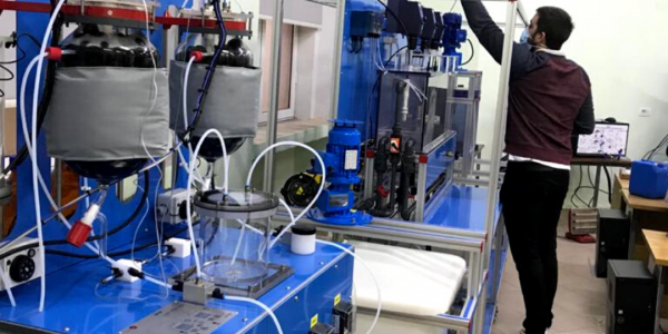
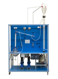
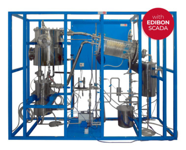
The Computer Controlled Liquid-Liquid Extraction Unit, "UELLC", designed by EDIBON, is a laboratory scale unit designed to study the separation of the components of liquid mixtures by contact of the mixture with an immiscible solvent in which these components are preferentially soluble.
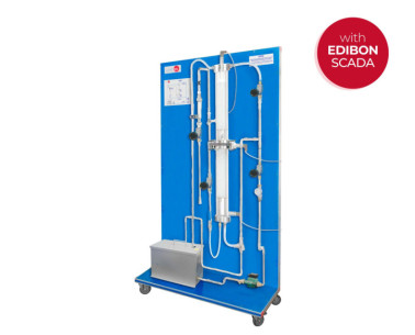
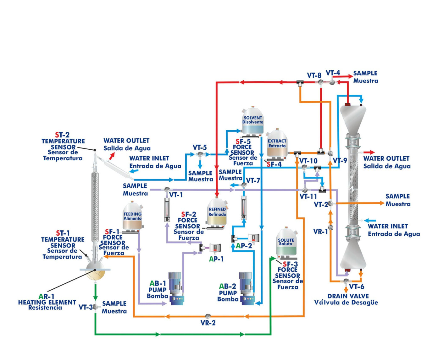
The extraction process is carried out in the glass liquid/liquid extraction column, which is composed of a jacketed glass packed column with two enlarged end sections. The joints between the three sections of the column are sealed with PTFE gaskets. The column is filled with glass Raschig rings that are supported on a perforated PVC plate.
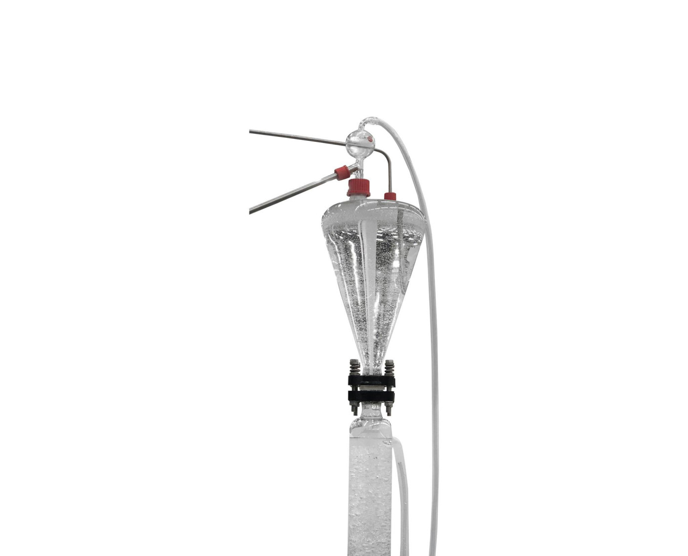
Feed for the column is stored in the feeding tank from where it is pumped by a computer controlled diaphragm pump. It passes through a flowmeter and enters the base section of the column via an injector mounted on it. Refine (phase with low content of solute) leaves the top of the column through a pipe and is collected in a refined tank.
The solvent supply tank provides the feed for a computer controlled diaphragm pump. The solvent is pumped and passes through a flowmeter, then enters the top of the column via an injector. Extract (phase with high content of solute) leaves the bottom of the column through a pipe and is collected in an extract tank. A drain valve is fitted in the extract line.
The supply circuits and product collection circuits include two pressure switches that switch off the pumps when the pressure is high, two sampling taps to collect samples, three-way directional valves to direct the different currents and a regulation valve to control the height of the interface.
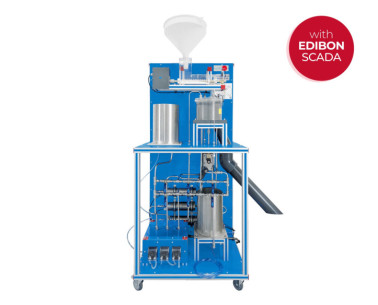
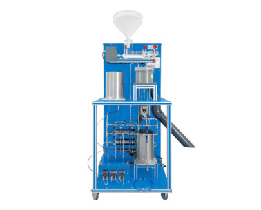
The distillation process is carried out in the distillation column boiler. The distillation column is made up of a glass section and contains Raschig rings made of glass. It is mounted close to the extraction column and fitted at such a height that the solute may be drained into the solute tank.
Heating is done by means of a computer controlled heating mantle (with control of the temperature in the column head) in the base of the boiler and the boiler temperature is indicated on a temperature sensor. The boiler lid is perforated where the distillation column is fitted and a pipeline allows to drain the extract from the extract tank. The boiler-solute tank circuit includes a sampling tap to collect samples.
The dissolvent vapor phase is condensed in the coolant column and re-cycled to the solvent tank to recover the dissolvent and to provide a closed circuit. Then, the solvent can be re-cycled continuously.
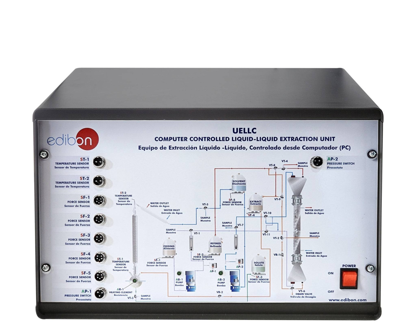
All storage tanks have force sensors to measure the mass in the five tanks (feed, refined, solvent, extract and solute) and to calculate the liquid volume.
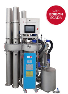
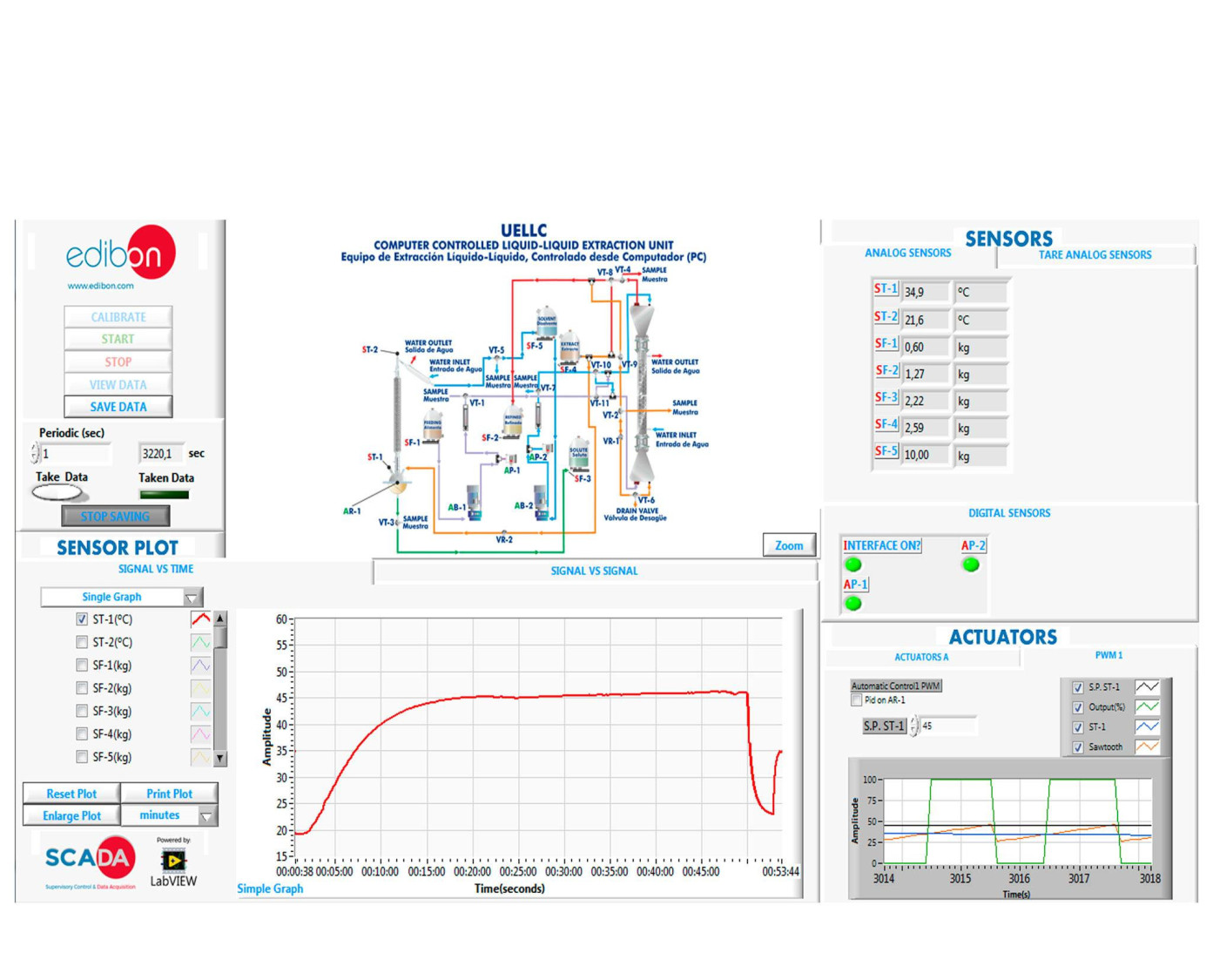
This Computer Controlled Unit is supplied with the EDIBON Computer Control System (SCADA), and includes: The unit itself + a Control Interface Box + a Data Acquisition Board + Computer Control, Data Acquisition and Data Management Software Packages, for controlling the process and all parameters involved in the process.
 Cookie preferences


 Catalog
 Tender Specifications


