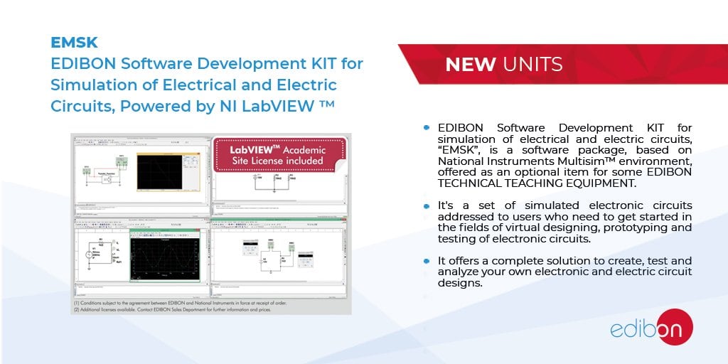
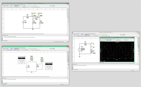
EDIBON Development KIT for Circuits Simulation, Powered by NI LabVIEW™ "EMSK", is a software package, based on National InstrumentsMultisim™ environment, offered as an optional item for some EDIBON TECHNICAL TEACHING EQUIPMENT. The "EMSK" is a set ofVirtual tools aimed to users who need to get started in the fields of virtual designing, prototyping, testing and PCB designing of electroniccircuits, including a set of examples with increasing complexity to help the students to perfom from basic to advanced actions.
The "EMSK" offers a complete solution to create, test, analyze and PCB designing of your own electronic and electric circuit designs, thevirtual components and instruments included are:
- Complete library of electronic components, more than 36,000, including diodes, logic gates, transistors, filters, different integratedcircuit to voltage regulation, temporization, led control, logic control, PID control, system simulation, close and open control loops,etc.
- Virtual components to power supply, digital signal generation, function generation, etc.
- Virtual instruments, with real interface, to perform a complete analysis of the designed circuits: voltmeters, ammeters, oscilloscopes,frequency analyzers, frequency counter, etc.
Additionally, the EDIBON Development KIT for Circuits Simulation, Powered by NI LabVIEW™ includes example circuits in order to test thespecific circuits of each EDIBON TECHNICAL TEACHING EQUIPMENT.
 쿠키 기본 설정

 목록
목록
 컨테스트 사양