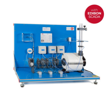
The Computer Controlled Reciprocating Compressor Unit, "HCRC", allows students to study and test a fluid power machine and to discover how the compressor flow rate relates to the pressure delivered by the compressor. The unit provides a detailed analysis of a compressor performance and allows to study the energy balance, efficiencies and thermodynamics of the compressor.
This unit consists of a small reciprocating compressor with an intake vessel. All controls and instrumentation are controlled from the computer.
The compressor speed is variable up to the maximum allowable for the compressor. The control of the compressor motor speed allows flexibility to match the compressor motor under different conditions.
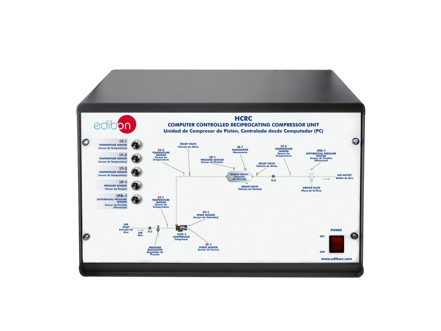
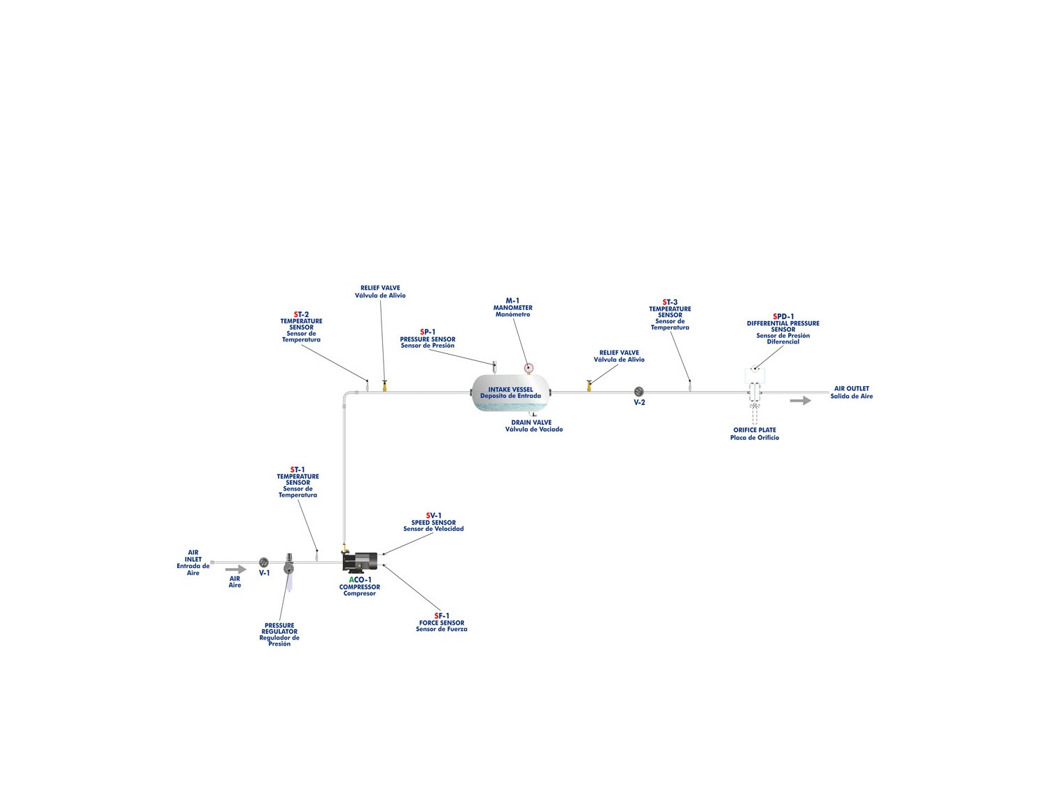
The inlet air passes through an air filter and pressure regulator to provide constant pressure, clean and water free air to the unit. The air enters the compressor, which delivers it under pressure to the intake vessel. The inlet air passes to an intake vessel to reduce intake pulsations and allows various inlet conditions to be established.
A valve releases pressure from the intake vessel to the atmosphere through an orifice plate. The valve sets the pressure in the intake vessel and, hence, the flow. The air passes through the orifice plate to determine the flow of the outlet air with a differential pressure sensor.
Pressures and temperatures are recorded using sensors at key points in the system. The temperature sensors are located at the inlet and outlet of the compressor, and upstream of the orifice plate. Pressure sensors measure the differential pressure in the orifice plate and pressure in the intake vessel.
The air throughput and the electrical power consumption of the compressor motor is also measured.
Instrumentation allows the motor electrical power consumption to be measured together with the speed and torque of the compressor motor. The product of the torque and speed gives the true shaft power.
The unit includes a manometer to show the intake vessel pressure if the main electricity fails.
Besides, the unit is equipped with safety devices (pressure relief valves, etc) to prevent misuse and to ensure a completely fail-safe operation for the students. For safety, all pressurized lines have relief valves.
This Computer Controlled Unit is supplied with the EDIBON Computer Control System (SCADA), and includes: The unit itself + a Control Interface Box + a Data Acquisition Board + Computer Control, Data Acquisition and Data Management Software Packages, for controlling the process and all parameters involved in the process.
 Preferensi cookie


 Katalog
 Spesifikasi Kontes


