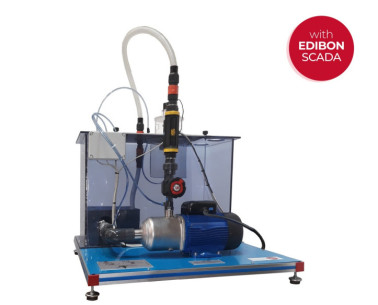
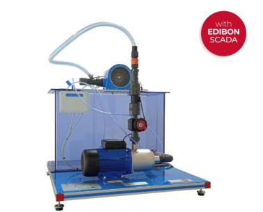
HMFAC Computer Controlled Axial Flow Turbomachines Unit
SISTEM INOVATIF
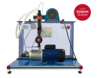
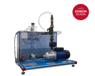
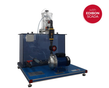
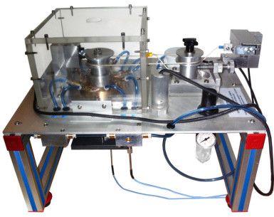
The Computer Controlled Axial Flow Turbomachines Unit, "HMFAC", allows the study of single-stage axial turbomachines, with interchangeable vanes for the study of both a pump and a turbine.
Ekspansi
Laboratorium
BERITA TERKAIT
GAMBARAN UMUM
The Computer Controlled Axial Flow Turbomachines Unit, "HMFAC", allows the study of single-stage axial turbomachines, with interchangeable vanes for the study of both a pump and a turbine.
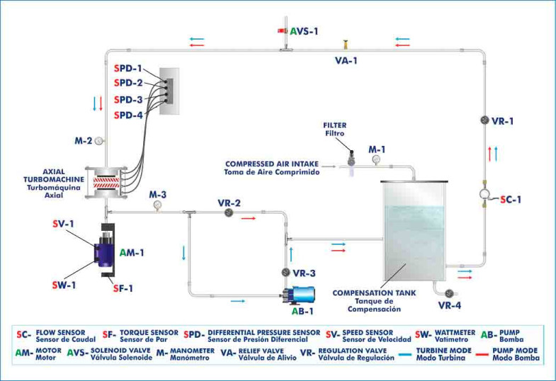
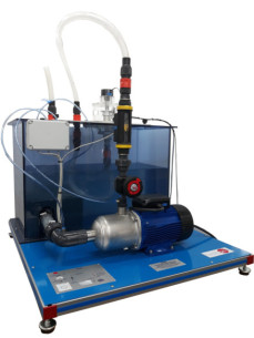
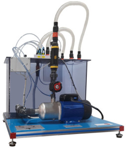
The main part of the unit is the axial turbomachine connected to a computer-controlled asynchronous motor. This turbomachine can be equipped with different sets of rotors/impellers and different sets of stators/distributor vane systems, to form a pump or a turbine configuration.
The unit consists of a closed water circuit with a compensation tank and a computer-controlled centrifugal pump, which through the activation of the compensation tank by means of compressed air allows the conversion of the turbomachine without water loss.
In the turbine mode, the asynchronous motor works as a generator, and the centrifugal pump generates the flow and pressure during its operation. The power generated by the turbine feed to this centrifugal pump. In pump mode, the asynchronous motor works as a drive.
The transparent casing allows seeing perfectly the flow processes through the different configurations of impeller/rotor and stator/vane system. In order to obtain the speed triangles for the different vane shapes, values will be taken by means of pressure sensors connected to a head to measure the direction and speed in the flow zone directly upstream, between and downstream, depending on the position where said head is placed, of rotor and stator or of impeller and vane system, so that the pressure development in the turbomachine is recorded.
To remove the remaining air from the piping system, a computer-controlled ventilation valve will be used, or an automatic relief valve will act, which is activated by system overpressure.
It is possible to carry out a cavitation study due to the use of different pressure levels.
The motor shaft is equipped with a speed sensor that measures the number of revolutions. The power of the drive is determined by a tilting bearing, equipped with a force sensor for measuring the motor torque, on which the asynchronous motor is mounted.
Two manometers that measure the pressures at the inlet and outlet of the turbomachine are included and the differential pressure sensors measure the differential pressure in the rotor, the impeller/stator and in the system of distributed blades. A regulation valve allows adjustment the flow, which is measured through a flow sensor.
This Computer Controlled Unit is supplied with the EDIBON Computer Control System (SCADA), and includes: The unit itself + a Control Interface Box + a Data Acquisition Board + Computer Control, Data Acquisition and Data Management Software Packages, for controlling the process and all parameters involved in the process.
LATIHAN DAN PRAKTEK PEDOMAN
LATIHAN PRAKTIS YANG DIANDAL TERMASUK DALAM PANDUAN
- Study of the turbomachine characteristics in turbine mode.
- Study of the turbomachine characteristics in pump mode.
- Obtaining the characteristic dimensionless numbers for each turbomachine.
- Determination of speed triangles and pressure developments for each set of vane wheels.
- Study of the importance of the shape of the blade in the efficiency and power.
- Determination of the energy exchange produced for each turbomachine.
- Study of the output angular momentum and its influence on power.
- Analysis of cavitation effects.
- Sensors calibration.
LEBIH BANYAK LATIHAN PRAKTIS YANG AKAN DILAKUKAN DENGAN UNIT
- Many students view results simultaneously. To view all results in real time in the classroom by means of a projector or an electronic whiteboard.
- Open Control, Multicontrol and Real Time Control. This unit allows intrinsically and/or extrinsically to change the span, gains, proportional, integral, derivative parameters, etc, in real time.
- The Computer Control System with SCADA and PID Control allow a real industrial simulation.
- This unit is totally safe as uses mechanical, electrical and electronic, and software safety devices.
- This unit can be used for doing applied research.
- This unit can be used for giving training courses to Industries even to other Technical Education Institutions.
- Control of the HMFAC unit process through the control interface box without the computer.
- Visualization of all the sensors values used in the HMFAC unit process.
- By using PLC-PI additional 19 more exercises can be done.
- Several other exercises can be done and designed by the user.
PERALATAN KOMPLEMENTER
Computer Controlled Francis Turbine
Computer Controlled Kaplan Turbine
Computer Controlled Radial Flow Turbine
Computer Controlled Axial Flow Turbine
Computer Controlled Experimental Reaction Turbine
Computer Controlled Experimental Impulse Turbine
Computer Controlled Hydraulic Turbines Modular Unit
Model Turbin Francis
Model Turbin Aliran Aksial
Model Turbin Aliran Radial
Model Turbin Pelton
KUALITAS

LAYANAN PURNA JUAL

 Preferensi cookie

