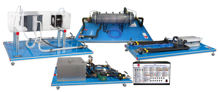
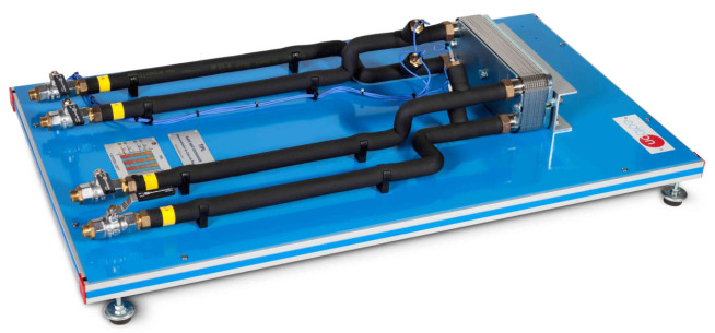
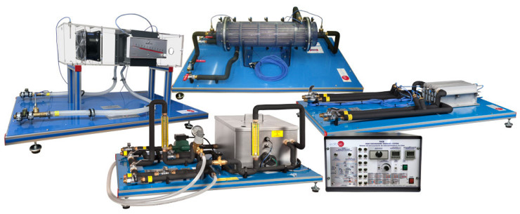
The "THER" consists of a refrigeration circuit, with the most common heat exchangers in refrigeration circuits. All the elements are clearly mounted in the front panel of the unit.
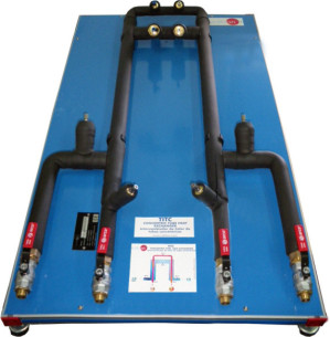
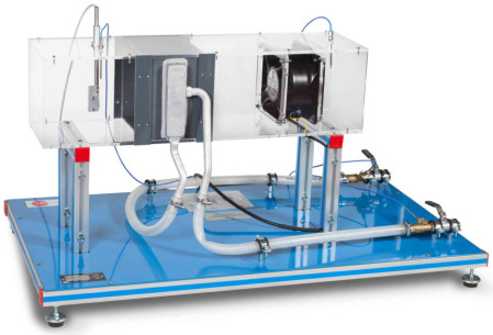
The evaporator is an air cooling finned tube heat exchanger and a water-heated plate heat exchanger.
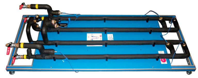
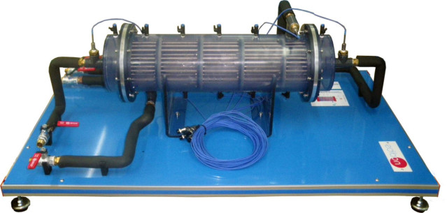
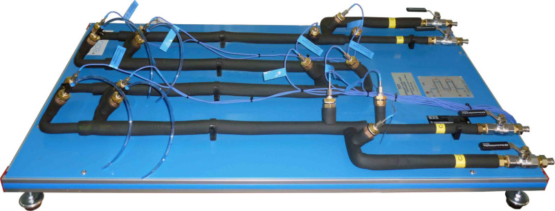
As condenser there is a water-cooled coaxial coil heat exchanger and as superheater, to study its influence, a tube heat exchanger.
The function of these exchangers is different depending on the type of system and the operation mode. The same exchanger can be used as evaporator and condenser, as for example the finned tube heat exchanger.
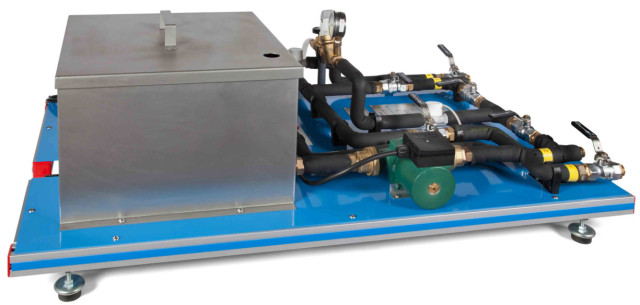
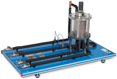
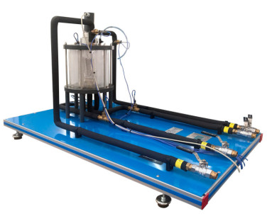
In order to cool or heat in the condenser or evaporator there is a water tank and a pump to impel the water to the heat exchanger.
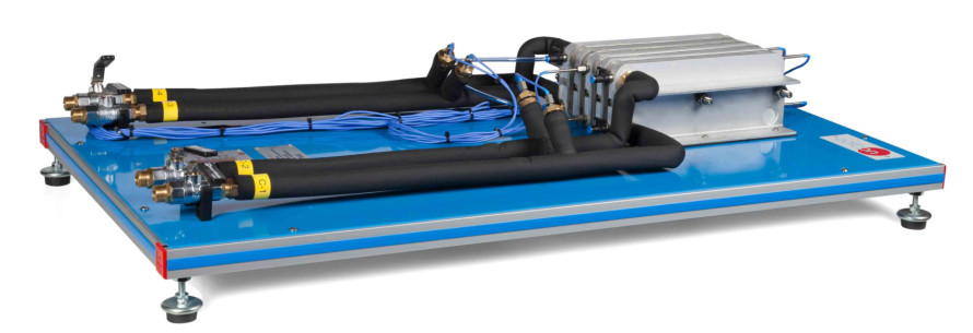
The unit includes two flow meters to know the heating water and cooling water used in the heat exchangers. Together with the temperature sensors located at the inlet and outlet, they allow the student to determine the exchanged energy fluxes.
Besides, there are manometers and temperature sensors at all relevant points of the system.
The unit includes basic elements of refrigeration circuits, such as compressor, receiver, filter to remove impurities, expansion element, low pressure switch and high pressure switch, etc.
 Cookie-Präferenzen

 Katalog
 Wettbewerbsspezifikationen